7.8.6 Binary Format
This is the fastest way to send points to the 4071 since it transfers the data point with only 2 characters. (It is also the least forgiving as far as getting the data sent correctly).
Each data point is a
The 16 bit value is in "two's complement" format, which represents a number from
8000 |
| ||||
| 0.0 | +.5 | +1.0 |
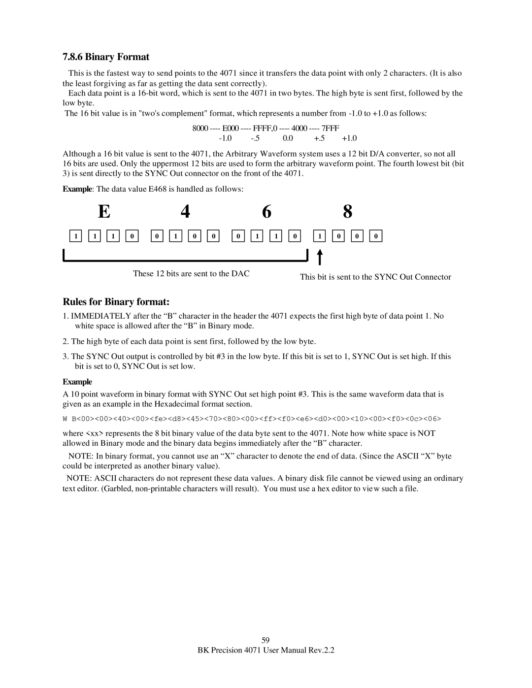
Although a 16 bit value is sent to the 4071, the Arbitrary Waveform system uses a 12 bit D/A converter, so not all 16 bits are used. Only the uppermost 12 bits are used to form the arbitrary waveform point. The fourth lowest bit (bit 3) is sent directly to the SYNC Out connector on the front of the 4071.
Example: The data value E468 is handled as follows:
E | 4 | 6 | 8 |
1
1
1
0
0 ![]()
![]() 1
1 ![]()
![]() 0
0 ![]()
![]() 0
0
0 ![]()
![]() 1
1 ![]()
![]() 1
1 ![]()
![]() 0
0
1
0
0
0
These 12 bits are sent to the DAC | This bit is sent to the SYNC Out Connector |
|
Rules for Binary format:
1.IMMEDIATELY after the “B” character in the header the 4071 expects the first high byte of data point 1. No white space is allowed after the “B” in Binary mode.
2.The high byte of each data point is sent first, followed by the low byte.
3.The SYNC Out output is controlled by bit #3 in the low byte. If this bit is set to 1, SYNC Out is set high. If this bit is set to 0, SYNC Out is set low.
Example
A 10 point waveform in binary format with SYNC Out set high point #3. This is the same waveform data that is given as an example in the Hexadecimal format section.
W B<00><00><40><00><fe><d8><45><70><80><00><ff><f0><e6><d0><00><10><00><f0><0c><06>
where <xx> represents the 8 bit binary value of the data byte sent to the 4071. Note how white space is NOT allowed in Binary mode and the binary data begins immediately after the “B” character.
NOTE: In binary format, you cannot use an “X” character to denote the end of data. (Since the ASCII “X” byte could be interpreted as another binary value).
NOTE: ASCII characters do not represent these data values. A binary disk file cannot be viewed using an ordinary text editor. (Garbled,
59
BK Precision 4071 User Manual Rev.2.2
