More on Phase Offsets
Phase Offsets are accomplished with a reset signal shared by all units. This signal tells all units to jump to a particular waveform point at the same time. By changing which point in the waveform is jumped to, the starting phase of the waveform may be adjusted. The 4071 has a phase offset field which allows the user to specify a starting phase from 0 degrees to 359.99 degrees. This phase is relative to the Master Unit’s waveform phase, which is always 0 degrees.
The 4071 translate the phase value entered on the LCD (from 0 to 359.99) to a starting address as follows:
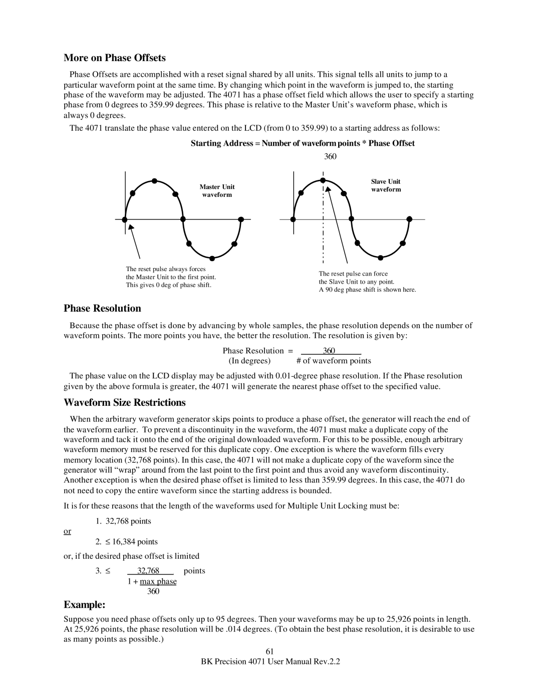
Starting Address = Number of waveform points * Phase Offset
360
Master Unit waveform
Slave Unit waveform
The reset pulse always forces the Master Unit to the first point. This gives 0 deg of phase shift.
The reset pulse can force the Slave Unit to any point.
A 90 deg phase shift is shown here.
Phase Resolution
Because the phase offset is done by advancing by whole samples, the phase resolution depends on the number of waveform points. The more points you have, the better the resolution. The resolution is given by:
Phase Resolution = |
| 360 | . |
|
(In degrees) | # of waveform points | |||
The phase value on the LCD display may be adjusted with
Waveform Size Restrictions
When the arbitrary waveform generator skips points to produce a phase offset, the generator will reach the end of the waveform earlier. To prevent a discontinuity in the waveform, the 4071 must make a duplicate copy of the waveform and tack it onto the end of the original downloaded waveform. For this to be possible, enough arbitrary waveform memory must be reserved for this duplicate copy. One exception is where the waveform fills every memory location (32,768 points). In this case, the 4071 will not make a duplicate copy of the waveform since the generator will “wrap” around from the last point to the first point and thus avoid any waveform discontinuity. Another exception is when the desired phase offset is limited to less than 359.99 degrees. In this case, the 4071 do not need to copy the entire waveform since the starting address is bounded.
It is for these reasons that the length of the waveforms used for Multiple Unit Locking must be:
1. 32,768 points
or
2. ≤ 16,384 points
or, if the desired phase offset is limited
3. ≤ 32,768 . points
1 + max phase
360
Example:
Suppose you need phase offsets only up to 95 degrees. Then your waveforms may be up to 25,926 points in length. At 25,926 points, the phase resolution will be .014 degrees. (To obtain the best phase resolution, it is desirable to use as many points as possible.)
61
BK Precision 4071 User Manual Rev.2.2