5.26 Voltage Controlled Oscillator (VCO) Mode
Introduction
The Voltage Controlled Oscillator mode generates signal, where frequency could be vary between two specified values using ext ernally supplied
VCO Mode Parameters
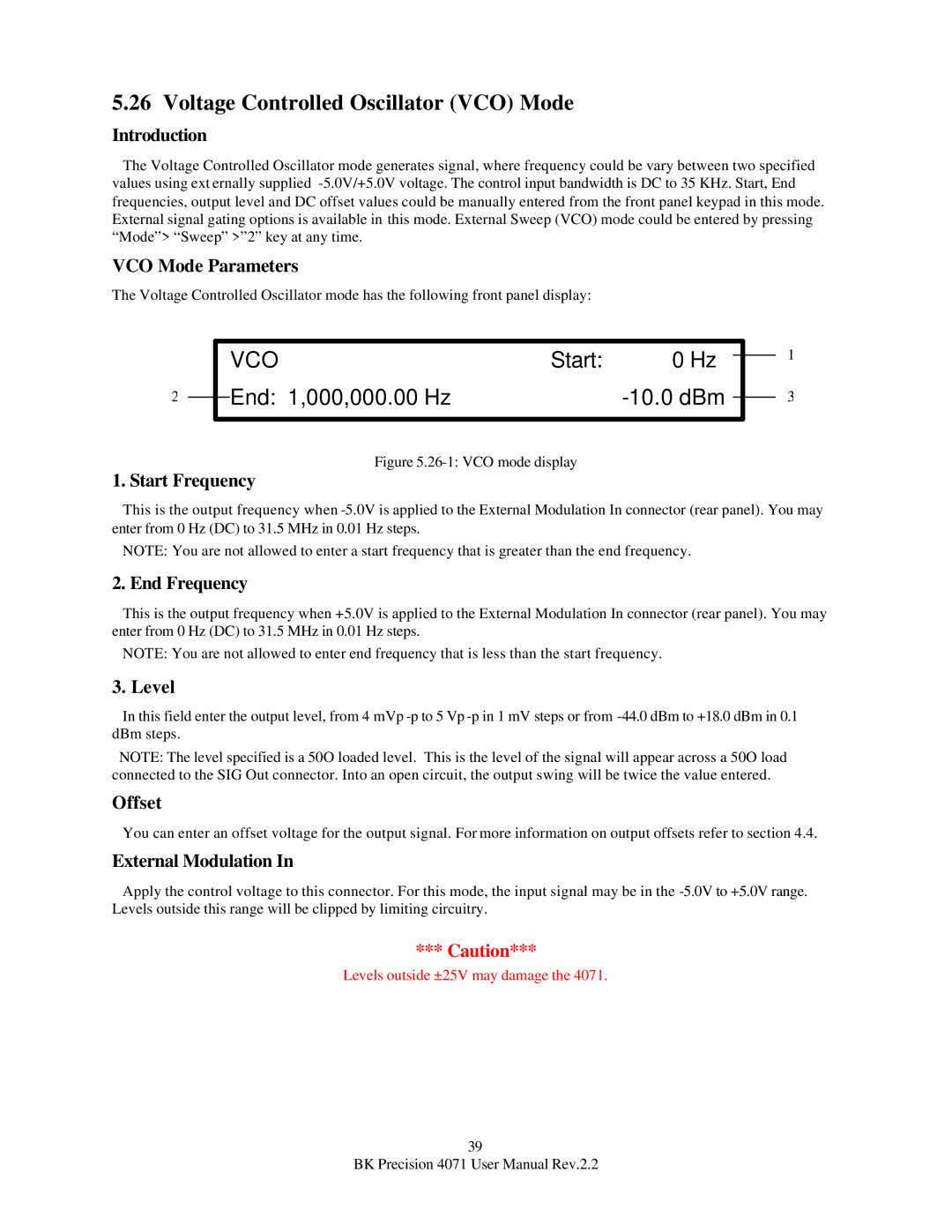
The Voltage Controlled Oscillator mode has the following front panel display:
|
|
| VCO | Start: | 0 Hz |
|
|
|
|
|
|
| |||
|
|
| End: 1,000,000.00 Hz |
|
|
|
|
2 |
|
|
|
|
| ||
|
|
|
|
| |||
|
|
|
|
|
|
|
|
Figure 5.26-1: VCO mode display
1. Start Frequency
1
3
This is the output frequency when
NOTE: You are not allowed to enter a start frequency that is greater than the end frequency.
2. End Frequency
This is the output frequency when +5.0V is applied to the External Modulation In connector (rear panel). You may enter from 0 Hz (DC) to 31.5 MHz in 0.01 Hz steps.
NOTE: You are not allowed to enter end frequency that is less than the start frequency.
3. Level
In this field enter the output level, from 4 mVp
NOTE: The level specified is a 50O loaded level. This is the level of the signal will appear across a 50O load connected to the SIG Out connector. Into an open circuit, the output swing will be twice the value entered.
Offset
You can enter an offset voltage for the output signal. For more information on output offsets refer to section 4.4.
External Modulation In
Apply the control voltage to this connector. For this mode, the input signal may be in the
*** Caution***
Levels outside ±25V may damage the 4071.
39
BK Precision 4071 User Manual Rev.2.2