1.1 Description
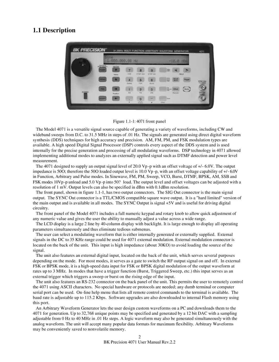
Figure 1.1-1: 4071 front panel
The Model 4071 is a versatile signal source capable of generating a variety of waveforms, including CW and wideband sweeps from D.C. to 31.5 MHz in steps of .01 Hz. The signals are generated using direct digital waveform synthesis (DDS) techniques for high accuracy and precision. AM, FM, PM, and FSK modulation types are available. A high speed Digital Signal Processor (DSP) controls every aspect of the DDS system and is used internally for the precise generation and processing of all modulating waveforms. DSP technology in 4071 allowed implementing additional modes to analyzes an externally applied signal such as DTMF detection and power level measurement.
The 4071 designed to supply an output signal level of 20.0 Vp -p with an offset voltage of +/- 6.0V. The output impedance is 50O; therefore the 50O loaded output level is 10.0 Vp -p, with an offset voltage capability of +/ - 6.0V in Function, Arbitrary and Pulse modes. In Sinewave, FM, PM, Sweep, VCO, Burst, DTMF, BPSK, AM, SSB and FSK modes 10Vp -p unload and 5.0 Vp -p into 50? load. The output level and offset voltages can be adjusted with a resolution of 1 mV. Output levels can also be specified in dBm with 0.1dBm resolution.
The front panel, shown in figure 1.1-1, has two output connectors. The SIG Out connector is the main signal output. The SYNC Out connector is a TTL/CMOS compatible square wave output. It is a "hard limited" version of the main output and is available in all modes. The SYNC Output is signal +5V and is useful for driving digital circuitry.
The front panel of the Model 4071 includes a full numeric keypad and rotary knob to allow quick adjustment of any numeric value and gives the user the ability to manually adjust a value across a wide range.
The LCD display is a large 2 line by 40-column display with backlight. It is large enough to display all operating parameters simultaneously and thus eliminate tedious submenus.
The user can select a modulating waveform that is either internally generated or externally supplied. External signals in the DC to 35 KHz range could be used for 4071 external modulation. External modulation connector is located on the back of the unit. This input is high impedance (about 30KO) to avoid loading the source of the signal.
The unit also features an external digital input, located on the back of the unit, which serves several purposes depending on the mode. For most modes, it serves as a gate to switch the RF output signal on and off. In external FSK or BPSK mode, it is a high-speed data input for FSK or BPSK digital modulation of the output waveform at rates up to 3 MHz. In modes that have a trigger function (Burst, Triggered Sweep, etc.) this input serves as an external trigger which triggers a sweep or burst on the rising edge of the input.
The unit also features an RS-232 connector on the back panel of the unit. This permits the user to remotely control the 4071 using ASCII characters. No special hardware or protocols are needed; any dumb terminal or computer serial port can be used. On -line help menu that lists all remote control commands to the terminal is available. The baud rate is adjustable up to 115.2 Kbps. Software upgrades are also downloaded to internal Flash memory using this port.
An Arbitrary Waveform Generator lets the user design custom waveforms on a PC and downloads them to the 4071 for generation. Up to 32,768 unique points may be specified and generated by a 12 bit DAC with a sampling adjustable from 0 Hz to 40 MHz in .01 Hz steps. A logic waveform may also be generated simultaneously with the analog waveform. The unit will accept many popular data formats for maximum flexibility. Arbitrary Waveforms may be conveniently saved to nonvolatile memory.
2
BK Precision 4071 User Manual Rev.2.2