INSTALLATION INSTRUCTIONS
RT16-10
ADDRESSABLE INFRARED ROUTER
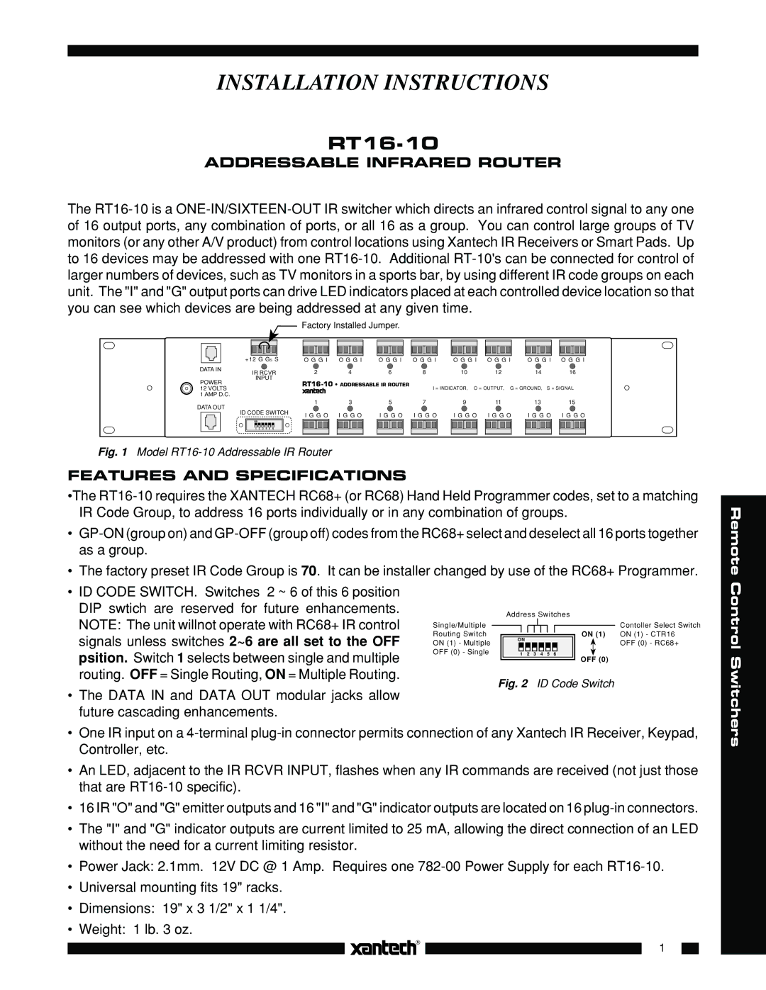
The
Factory Installed Jumper.
|
|
|
|
|
|
|
|
|
|
|
|
|
|
|
|
|
|
|
|
|
|
|
|
|
|
|
|
|
|
|
|
|
|
|
|
|
|
|
|
|
|
|
|
|
|
|
|
|
|
|
|
|
|
|
|
|
|
|
|
|
|
|
|
|
|
|
|
|
|
|
|
|
|
|
|
|
|
|
|
|
|
|
|
|
|
|
|
|
|
|
|
|
|
|
|
|
|
|
|
|
|
|
|
|
|
|
|
|
|
|
|
|
|
|
|
|
|
|
|
|
|
|
|
|
|
|
|
|
|
|
|
|
|
|
|
|
|
|
|
|
|
|
|
|
|
|
|
|
|
|
|
|
|
|
|
|
|
|
|
|
|
|
|
|
| +12 G GS S |
| O G G I |
| O G G I |
| O G G I | O G G I |
| O G G I |
| O G G I |
| O G G I |
| O G G I | ||||||||||||||||||||||||||||||
DATA IN |
| IR RCVR | 2 |
|
| 4 |
|
| 6 |
|
|
| 8 |
|
| 10 |
| 12 |
| 14 |
| 16 |
| |||||||||||||||||||||||||||||
|
|
|
|
|
|
|
|
|
|
|
|
|
|
|
|
|
|
|
|
| ||||||||||||||||||||||||||||||||
POWER |
| INPUT |
|
|
|
|
|
|
|
|
|
|
|
|
|
|
|
|
|
|
|
|
|
|
|
| ||||||||||||||||||||||||||
|
|
|
|
|
|
|
|
| I = INDICATOR, O = OUTPUT, G = GROUND, S = SIGNAL | |||||||||||||||||||||||||||||||||||||||||||
12 VOLTS |
|
|
|
|
|
|
|
|
|
|
|
|
|
|
|
|
|
|
|
|
|
|
|
|
| |||||||||||||||||||||||||||
1 AMP D.C. |
|
|
|
|
|
|
|
|
|
|
|
|
|
|
|
|
|
|
|
|
|
|
|
|
|
|
|
|
|
|
|
|
|
|
|
|
|
|
|
|
|
|
|
|
|
| ||||||
DATA OUT |
|
|
|
|
|
| 1 |
|
| 3 |
|
| 5 |
|
|
| 7 |
|
| 9 |
|
| 11 |
| 13 |
| 15 |
| ||||||||||||||||||||||||
ID CODE SWITCH |
|
|
|
|
|
|
|
|
|
|
|
|
|
|
|
|
|
|
|
|
|
|
|
|
|
|
|
|
|
|
|
|
|
|
|
|
|
|
|
| ||||||||||||
|
|
|
|
|
|
|
| I G G O I G G O |
| I G G O I G G O |
| I G G O I G G O |
| I G G O I G G O | ||||||||||||||||||||||||||||||||||||||
|
|
|
|
|
|
|
|
|
|
|
|
|
|
|
|
| ||||||||||||||||||||||||||||||||||||
ON |
|
|
|
|
|
1 | 2 | 3 | 4 | 5 | 6 |
Fig. 1 Model RT16-10 Addressable IR Router
FEATURES AND SPECIFICATIONS
•The
•
•The factory preset IR Code Group is 70. It can be installer changed by use of the RC68+ Programmer.
Remote
•ID CODE SWITCH. Switches 2 ~ 6 of this 6 position DIP swtich are reserved for future enhancements. NOTE: The unit willnot operate with RC68+ IR control signals unless switches 2~6 are all set to the OFF psition. Switch 1 selects between single and multiple routing. OFF = Single Routing, ON = Multiple Routing.
•The DATA IN and DATA OUT modular jacks allow future cascading enhancements.
|
| Address Switches |
| ||||||||||||||
Single/Multiple |
|
|
|
|
|
|
|
|
|
|
|
|
|
|
|
| Contoller Select Switch |
Routing Switch |
|
|
|
|
|
|
|
|
|
|
|
|
|
| ON (1) | ON (1) - CTR16 | |
|
|
|
|
|
|
|
|
|
|
|
|
|
| ||||
ON (1) - Multiple | ON |
|
|
|
|
| OFF (0) - RC68+ |
|
|
|
|
|
| ||
OFF (0) - Single | 1 | 2 | 3 | 4 | 5 | 6 | OFF (0) |
|
|
|
|
|
|
|
Fig. 2 ID Code Switch
Control Switchers
•One IR input on a
•An LED, adjacent to the IR RCVR INPUT, flashes when any IR commands are received (not just those that are
•16 IR "O" and "G" emitter outputs and 16 "I" and "G" indicator outputs are located on 16
•The "I" and "G" indicator outputs are current limited to 25 mA, allowing the direct connection of an LED without the need for a current limiting resistor.
•Power Jack: 2.1mm. 12V DC @ 1 Amp. Requires one
•Universal mounting fits 19" racks.
•Dimensions: 19" x 3 1/2" x 1 1/4".
•Weight: 1 lb. 3 oz.
1
