1000, 1800 specifications
Xantrex Technology offers a range of power inverters that cater to both recreational and professional needs, with the Xantrex 1800 and 1000 models being among the most popular in their lineup. These inverters are specially designed to convert DC power from batteries into clean, pure sine wave AC power, making them suitable for running sensitive electronic devices and appliances.The Xantrex 1800 is a robust inverter that delivers 1800 watts of continuous power and 3600 watts of peak power. This makes it ideal for powering essential appliances like refrigerators, microwaves, and power tools. Its compact design allows for easier installation in various settings such as RVs, boats, and off-grid homes.
On the other hand, the Xantrex 1000 inverter is designed for lower power requirements, offering 1000 watts of continuous power and 2000 watts of peak power. It is perfect for powering small appliances, electronics, and gadgets, making it a great choice for weekend campers and those who require less energy capacity.
Both models feature advanced technologies, including low idle power draw, which ensures that energy is conserved when the inverter is not actively powering devices. They also include overload protection, ensuring the inverter shuts down automatically if the power exceeds its limits, thus preventing damage to the unit or connected devices.
Another hallmark of Xantrex inverters is their user-friendly interface. The LED indicator lights provide clear status updates on the power output and inverter operation, making it easy for users to monitor performance at a glance. Additionally, both models feature various safety protocols, including short circuit and over-temperature protection, to enhance operational safety.
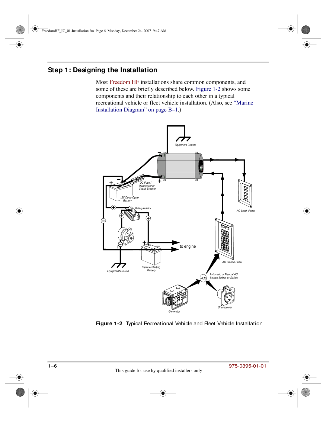
Installation is straightforward, thanks to the provided mounting options and wiring accessories. The units are designed to withstand harsh environments, with durable casings that enhance longevity and resilience.
In summary, the Xantrex 1800 and 1000 models offer reliable power solutions for a variety of applications. Their combination of high-quality sine wave output, advanced safety features, and user-friendly operation makes them a top choice for anyone seeking dependable off-grid power. With Xantrex, users can trust that they are investing in products engineered for performance and durability in an ever-increasing range of power needs.

