PCY60
 PCY60 DISASSEMBLY PROCEDURE
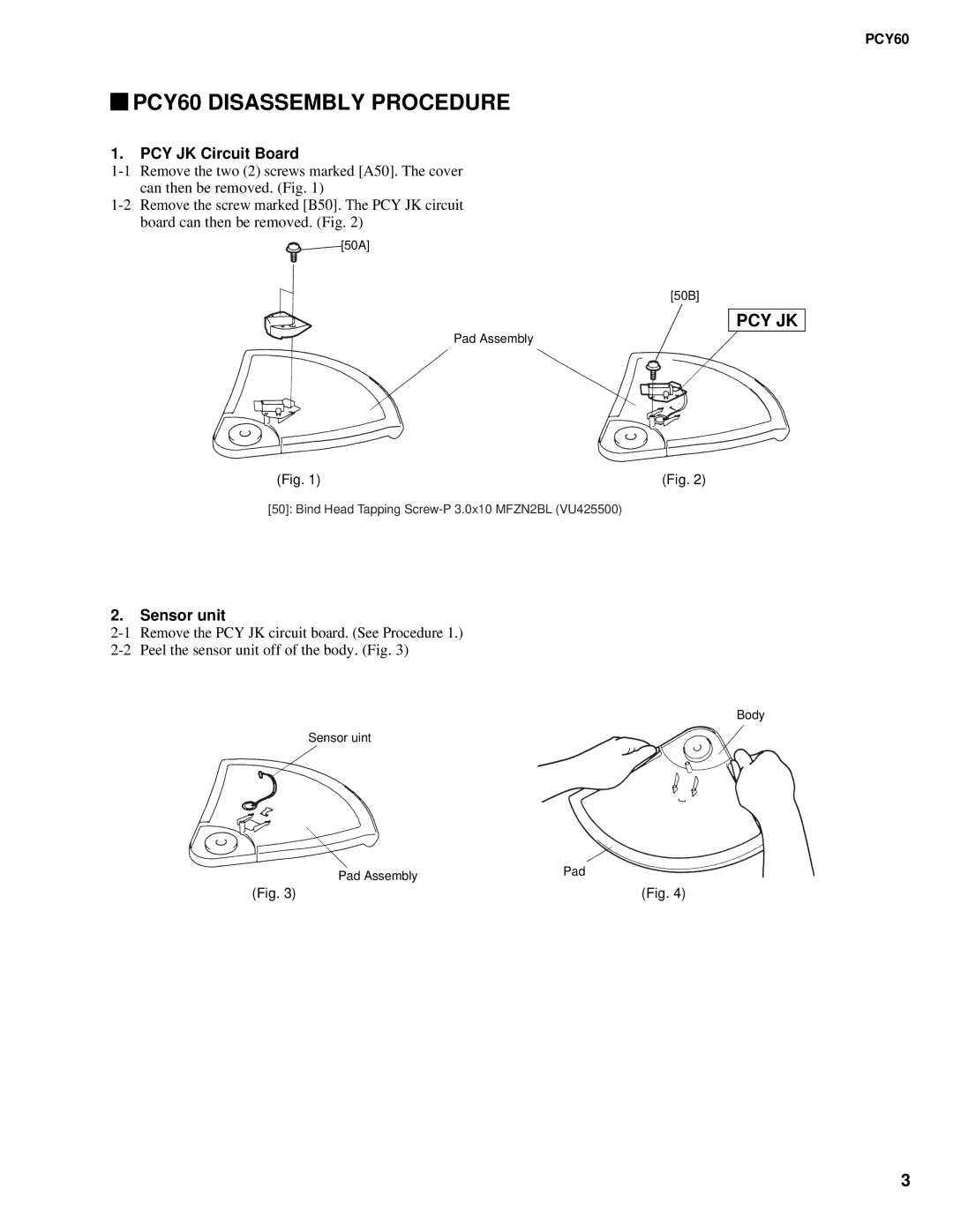
1.PCY JK Circuit Board
[50A]
[50B]
PCY JK
Pad Assembly
(Fig. 1) | (Fig. 2) |
[50]: Bind Head Tapping
2.Sensor unit
Body
Sensor uint
| Pad Assembly | Pad |
|
| |
(Fig. 3) |
| (Fig. 4) |
3
PCY60
[50A]
[50B]
Pad Assembly
(Fig. 1) | (Fig. 2) |
[50]: Bind Head Tapping
Body
Sensor uint
| Pad Assembly | Pad |
|
| |
(Fig. 3) |
| (Fig. 4) |
3