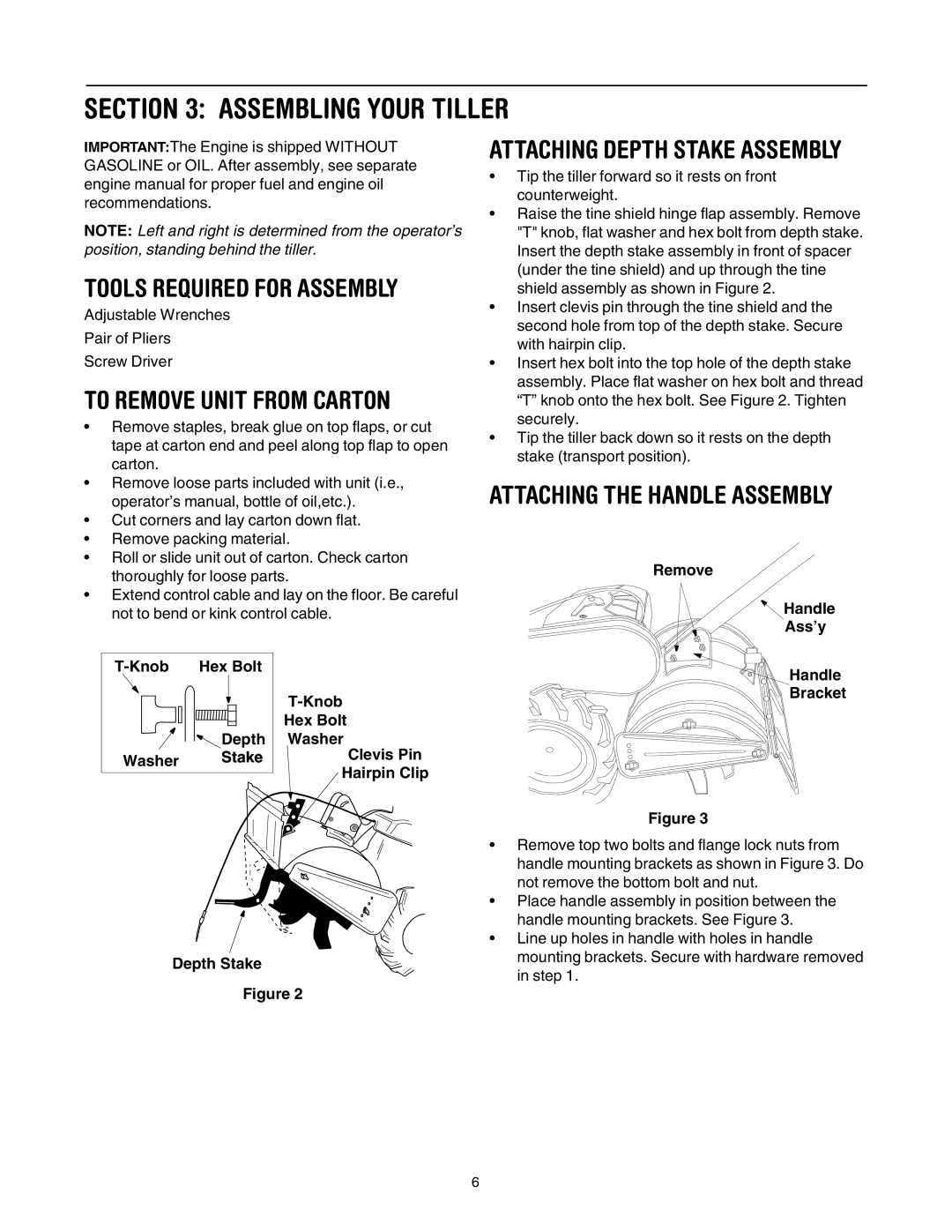
RT65 specifications
The Yard-Man RT65 is a versatile and robust lawn tractor designed to meet the mowing and gardening needs of homeowners with medium to large properties. Equipped with a powerful engine and a series of features, it’s built for efficiency and ease of use, ensuring that every cutting session is both productive and enjoyable.One of the most notable features of the Yard-Man RT65 is its 65-inch cutting deck. This generous size allows for a wider swath of grass to be cut in a single pass, significantly reducing mowing time. The cutting deck is made from durable materials that withstand the rigors of regular use, providing longevity and reliability to the user. The adjustable cutting height feature gives homeowners the ability to customize the grass length according to personal preferences and seasonal requirements.
The RT65 is powered by a robust engine, usually a dependable Briggs & Stratton or a similarly positioned manufacturer. This reliable engine ensures sufficient power to tackle tough mowing tasks, while maintaining fuel efficiency. The tractor is designed with user comfort in mind, featuring an ergonomic seat that provides a comfortable ride even during extended mowing sessions. The controls are intuitively placed, allowing for seamless operation without distraction.
In terms of technology, the Yard-Man RT65 boasts an automatic transmission system, offering a smooth driving experience. This feature allows the mower to adjust its speed seamlessly, making it easier to navigate through varying terrain. The turning radius is also commendable, enabling homeowners to maneuver around tight corners and obstacles in the yard with ease.
Safety features are a priority in the design of the RT65, which typically includes a parking brake and a safety cut-off that stops the blades when the operator leaves the seat. This ensures peace of mind, especially when children or pets are present in the vicinity.
Moreover, the RT65 is compatible with various attachments and accessories. Whether it's a bagger for grass clippings, a snow plow for winter maintenance, or a mulcher for given lawn care treatment, the versatility of this lawn tractor makes it a multi-functional tool for year-round yard work.
In summary, the Yard-Man RT65 combines power, efficiency, and user-friendly features in a compact package. Its impressive cutting capability, reliable engine, and thoughtful design characteristics make it a valuable addition to any homeowner's lawn care arsenal, ensuring well-maintained lawns with minimal effort.

