SECTION 2: ASSEMBLING YOUR TILLER

NOTE: This operator’s guide covers three different model tillers. Models 340 thru 345 have forward tine drive only. Model 390 has both forward and reverse tine drive. Follow only the instructions which pertain to your model tiller. See the model plate on your tiller for the correct model number.

IMPORTANT:This unit is shipped WITHOUT GASOLINE or OIL. After assembly, see separate engine manual for proper fuel and engine oil recommendations.

NOTE: Left and right is determined from the operator's position, standing behind the tiller.

Removing Unit From Carton

Remove staples, break glue on top flaps, or cut tape at carton end and peel along top flap to open carton.

Remove all loose parts included with unit (i.e., operator’s manual, etc.)

Cut corners and lay carton down flat.

Remove packing material.

Roll or slide unit out of carton. Check carton thoroughly for loose parts.

Extend control cable(s) to the rear of the tiller and lay them on the floor. Be careful not to bend or kink control cable(s).

Setting Up Your Tiller

Attaching The Tailpiece And Depth Stake

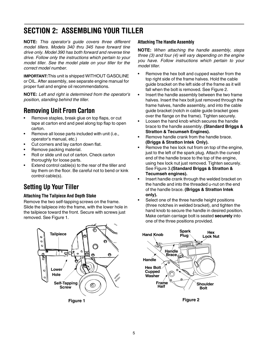
Remove the two self-tapping screws on the frame. Slide the tailpiece into the frame, with the lower hole in the tailpiece toward the front. Secure with screws just removed. See Figure 1.

Tailpiece

Lower

Hole

Self-Tapping

Screw

Attaching The Handle Assembly

NOTE: When attaching the handle assembly, steps three (3) and four (4) will vary depending on the engine you have. Follow instructions which pertain to your model tiller.

Remove the hex bolt and cupped washer from the top right side of the frame halves. Hold the cable guide bracket on the left side of the frame as it will fall when the bolt is removed. See Figure 2.

Insert the handle assembly between the two frame halves. Insert the hex bolt just removed through the frame halves, handle assembly, and into the cable guide bracket (notch in cable guide bracket goes over the flange on the frame). Tighten securely.

Loosen the hand knob which secures the handle brace to the handle assembly. (Standard Briggs &

Stratton & Tecumseh Engines).

Remove handle crank from the handle brace.

(Briggs & Stratton Intek Only).

Remove the hex lock nut from on top of the engine, just to the left of the spark plug. Attach the curved end of the handle brace to the top of the engine, using hex lock nut just removed. Tighten securely. See Figure 3.(Standard Briggs & Stratton &

Tecumseh engines).

Insert handle crank through the welded bracket on the handle and into the threaded u-nut on the end of the handle brace. (Briggs & Stratton Intek only).

Select one of the three handle height positions (three notches in welded bracket), and tighten the hand knob to secure the handle in desired position. Make certain carriage bolt is seated securely into one of the three positions provided.

Hand Knob

Spark

Hex

Plug

Lock Nut

Handle

Brace

Handle

Hex Bolt

Cupped

Washer

Frame

Shoulder

Half

Bolt


Figure 1

Figure 2

5

Page 5
Image 5
Yard Machines 390 Assembling Your Tiller, Removing Unit From Carton, Setting Up Your Tiller, Attaching The Handle Assembly

390 specifications

The Yard Machines 390 is a robust and versatile lawn mower designed to meet the demands of both residential and commercial users. With its powerful features and advanced technologies, the Yard Machines 390 delivers exceptional performance, making lawn care an easier and more efficient task.

At the heart of the Yard Machines 390 is a reliable engine. The 390cc engine provides ample power to tackle even the toughest mowing jobs. This engine is engineered for optimal performance, ensuring a smooth and consistent cut across various grass types. Its efficient fuel consumption not only extends the operation time but also reduces the frequency of refueling.

One of the standout features of the Yard Machines 390 is its cutting deck. The 21-inch cutting deck is crafted from durable materials, allowing for longevity and resilience against wear and tear. The deck is designed for superior airflow, ensuring a clean and even cut every time. Additionally, the mower offers multiple cutting height positions, allowing users to customize their mowing height according to their preference and the type of grass being cut.

The Yard Machines 390 is equipped with a self-propelled drive system, which significantly reduces the effort required by the user. This feature is particularly beneficial on hilly terrain or uneven surfaces, providing enhanced maneuverability and control. The adjustable speed settings further allow users to tailor the mowing pace to their comfort level.

An additional characteristic of the Yard Machines 390 is its ease of maintenance. The mower is designed for simple access to vital components, making routine maintenance tasks such as oil changes and blade sharpening straightforward and hassle-free. The machine's durable construction also contributes to its reliability and reduces the need for frequent repairs.

Moreover, the Yard Machines 390 incorporates safety features to protect users during operation. The operator presence control ensures that the engine stops immediately if the user loses control of the mower, minimizing the risk of accidents.

In summary, the Yard Machines 390 is a powerful, efficient, and user-friendly lawn mower that combines advanced technology with practical features. Its robust engine, versatile cutting deck, self-propelled drive, and safety measures make it an excellent choice for anyone looking to maintain a pristine lawn with minimal effort. Whether you are a homeowner or a professional landscaper, the Yard Machines 390 is designed to deliver exceptional results.