OPERATION
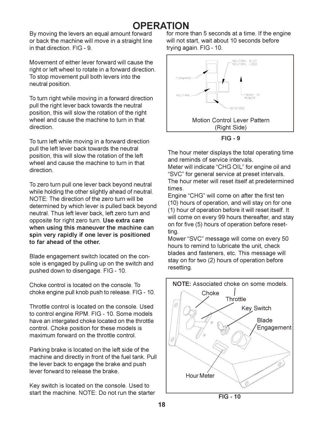
By moving the levers an equal amount forward | for more than 5 seconds at a time. If the engine | |
or back the machine will move in a straight line | will not start, wait about 10 seconds before | |
in that direction. FIG - 9. | trying again. FIG - 10. | |
Movement of either lever forward will cause the |
| |
right or left wheel to rotate in a forward direction. |
| |
To stop movement pull both levers into the |
| |
neutral position. |
| |
To turn right while moving in a forward direction |
| |
pull the right lever back towards the neutral |
| |
position, this will slow the rotation of the right |
| |
wheel and cause the machine to turn in that | Motion Control Lever Pattern | |
direction. | (Right Side) | |
To turn left while moving in a forward direction | FIG - 9 | |
| ||
pull the left lever back towards the neutral | The hour meter displays the total operating time | |
position, this will slow the rotation of the left | ||
and reminds of service intervals. | ||
wheel and cause the machine to turn in that | ||
Meter will indicate “CHG OIL” for engine oil and | ||
direction. | ||
“SVC” for general service at preset intervals. | ||
| ||
To zero turn pull one lever back beyond neutral | The hour meter will reset itself at predetermined | |
times. | ||
while holding the other slightly ahead of neutral. | ||
Engine “CHG” will come on after the first ten | ||
NOTE: The direction of the zero turn will be | ||
(10) hours of operation, and will stay on for one | ||
determined by which lever is pulled back beyond | ||
(1) hour of operation before it will reset itself. It | ||
neutral. Thus left lever back, left zero turn and | ||
will come on every 99 hours thereafter, and stay | ||
opposite for right zero turn. Use extra care | ||
on for five (5) hours of operation before reset- | ||
when using this maneuver the machine can | ||
ting. | ||
spin very rapidly if one lever is positioned | ||
Mower “SVC” message will come on every 50 | ||
to far ahead of the other. | ||
hours to remind to lubricate the unit, check | ||
| ||
Blade engagement switch located on the con- | blades and fasteners, etc. This message will | |
stay on for two (2) hours of operation before | ||
sole is engaged by pulling up on the switch and | ||
resetting. | ||
pushed down to disengage. FIG - 10. | ||
| ||
Choke control is located on the console. To | NOTE: Associated choke on some models. | |
choke engine pull knob push to release. FIG - 10. | Choke | |
Throttle control is located on the console. Used | Throttle | |
Key Switch | ||
to control engine RPM. FIG - 10. Some models | Blade | |
have an intergated choke located on the throttle | ||
control. Choke position for these models is | Engagement | |
maximum forward on the throttle control. |
| |
Parking brake is located on the left side of the |
| |
machine and directly in front of the fuel tank. Pull |
| |
the lever back to engage the brake and push |
| |
lever forward to release the brake. | Hour Meter | |
| ||
Key switch is located on the console. Used to |
| |
start the machine. NOTE: Do not run the starter | FIG - 10 | |
|
18
