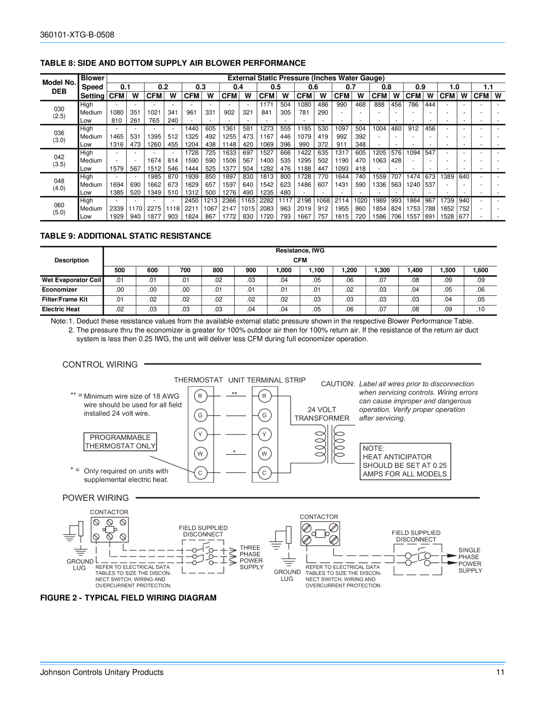
D2EB030 specifications
The York D2EB030 is a prominent model in the realm of commercial climate control systems, specifically designed to cater to medium to large-scale applications. This equipment stands out due to its high efficiency and reliability, ensuring optimal thermal comfort in various settings, from office buildings to warehouses.One of the main features of the York D2EB030 is its capacity. With a nominal cooling capacity of around 30 tons, it is well-suited for substantial cooling demands. This makes it an excellent choice for facilities that require consistent and effective temperature management. Additionally, it offers variable refrigerant flow (VRF) operation, which allows for simultaneous heating and cooling in different zones, providing enhanced comfort and flexibility.
The D2EB030 is equipped with advanced inverter technology. This feature allows the compressor to modulate its speed based on the cooling or heating needs of the environment, leading to significant energy savings. By adjusting the refrigerant flow and maintaining more stable indoor temperatures, the inverter-driven compressor reduces operational costs and energy consumption compared to traditional systems.
Additionally, the unit boasts a range of control options. It can be integrated with smart building management systems, allowing for remote monitoring and control through mobile devices or computers. This connectivity enables facility managers to optimize operation schedules, perform maintenance checks, and respond quickly to any issues, enhancing overall efficiency.
In terms of build quality, the York D2EB030 showcases robust construction, designed to withstand the rigors of commercial use. Its corrosion-resistant materials ensure longevity and reduce maintenance requirements. The system is also designed with sound-dampening features, resulting in quieter operation—a crucial aspect in noise-sensitive environments.
Among its environmental considerations, the unit utilizes refrigerants that are compliant with global regulations, contributing to lower greenhouse gas emissions. Moreover, its design promotes higher energy efficiency ratios (EER) and seasonal energy efficiency ratios (SEER), which are critical for reducing the overall carbon footprint.
In summary, the York D2EB030 stands out in the market for its combination of robust features, advanced technologies, and energy efficiency, making it a top choice for commercial climate control solutions. With its capacity, smart technology integration, and environmental considerations, this model is tailored to meet the dynamic needs of modern facilities while ensuring cost-effectiveness and sustainability.

