FORM
INSTALLATION
2.Frame around the perimeter of the unit as required for securing the drywall. See Table 1 below for drywall openings.
TABLE 1 - DRYWALL OPENINGS
MODEL NUMBER | DRYWALL CUTOUT DIM | |
HT x WD | ||
| ||
3YWC | 28 x 42 | |
4YWC | 28 x 50 | |
6YWC | 28 x 58 | |
8YWC | 28 x 66 | |
10YWC | 28 x 74 | |
12YWC | 28 x 82 |
3.Mount the unit in its permanent location, making sure it is level to insure proper drainage and operation (two 1/2” holes have been provided on each end of the unit for securing the unit to the wall studs).
4.After the drywall has been installed, recheck to make sure the unit’s front panel is flush with the exterior drywall surface. Shimming of the unit may be required to get a seal between the unit and panel.
5.Install the wall panel to the front of the unit using the
6.Remove the lower return air grille to get access to the filter.
7.See Fig. 2 for unit details and dimensions.
Hung on a Closet Wall
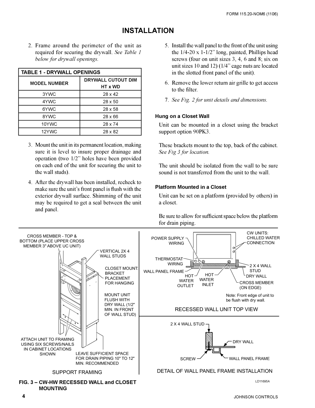
Unit can be mounted in a closet using the bracket support option 90PK3.
These brackets mount to the top, back of the cabinet. See Fig 3 for location.
The unit should be isolated from the wall to be sure sound is not transferred from the unit to the wall.
Platform Mounted in a Closet
Unit can be set on a platform (provided by others) in a closet.
Be sure to allow for sufficient space below the platform for drain piping.
CROSS MEMBER - TOP &
BOTTOM (PLACE UPPER CROSS
MEMBER 3" ABOVE UC UNIT)
VERTICAL 2X 4
WALL STUDS
CLOSET MOUNT:
BRACKET
PLACEMENT
FOR HANGING
MOUNT UNIT
FLUSH WITH
DRY WALL (1/2"
MIN. IN FRONT
OF WALL STUD)
|
|
|
|
|
|
|
| |
|
|
|
|
|
|
|
| |
|
|
|
|
|
|
|
| |
|
|
|
|
|
|
|
| |
|
|
|
|
|
|
|
| |
ATTACH UNIT TO FRAMING |
|
|
|
|
| |||
|
|
|
|
| ||||
|
|
|
|
| ||||
USING SIX SCREWS/NAILS |
|
|
|
|
| |||
IN CABINET LOCATIONS |
|
|
|
|
| |||
LEAVE SUFFICIENT SPACE | ||||||||
SHOWN | ||||||||
|
|
| FOR DRAIN PIPING 10" TO 12" | |||||
|
|
| MIN. RECOMMENDED | |||||
SUPPORT FRAMING
FIG. 3 – CW-HW RECESSED WALL and CLOSET MOUNTING
|
| CW UNITS: | |
POWER SUPPLY |
| CHILLED WATER | |
WIRING |
| CONNECTION | |
THERMOSTAT |
|
| |
WIRING |
| 2 X 4 WALL | |
|
| ||
WALL PANEL FRAME | HOT | STUD | |
HOT | DRY WALL | ||
WATER | WATER | CROSS MEMBER | |
OUTLET | INLET | ||
(ON EDGE) | |||
|
|
Note: Front edge of unit to be flush with dry wall.
RECESSED WALL UNIT TOP VIEW
2 X 4 WALL STUD
| DRY WALL |
SCREW | WALL PANEL FRAME |
DETAIL OF WALL PANEL FRAME INSTALLATION
LD11695A
4 | JOHNSON CONTROLS |