FORM 115.20-NOM4 (105)

INSTALLATION

PIPING

The supply and return piping must be adequately sized to meet the design water flow requirements as specified for the specific installation (see table 3 for connection sizes). All chilled water piping must be insulated to prevent condensation. It is also recommended that all piping be insulated to prevent freezing when piping is run in an unconditioned space.

Coil freeze protection is recommended for applications where the fan coil is located in ambient air locations (attics, crawl spaces, etc.) or within structures that may be unoccupied during freez- ing conditions. Consult the factory for additional information.

PIPING PRECAUTIONS

Flush all piping prior to connection to remove all debris.

Use wet cotton rags to cool valve bodies when soldering.

Open all valves (midway for hand valves, manually open on motorized valves) prior to soldering.

When soldering to bronze or brass, heat the piping while in the socket/cup and begin introducing the solder when the flux boils rapidly. Avoid direct flame into the solder joint.

Heat can only be applied to the cup of the valve body for a min i mal time before damage occurs (even with the use of wet rags.

Avoid rapid quenching of solder joints, as this will produce joints of inferior quality.

Connect all piping per accepted industry standards and observe all regulations governing installation of piping systems. When all connections are complete, the system must be pressure tested. Repair any solder joint leaks and gently tighten any leaking valve packing nuts and piping accessories as required. Hydronic systems are not designed to hold pressurized air and should only be tested with water.

When connecting piping or valve kits to fan coil units, do not bend or reposition the coil header tubing for alignment purposes. This could cause a tubing fracture resulting in a water leak when water pressure is applied to the system.

DRAIN PIPING

Condensate drain lines must be installed with adequate slope away from the unit to assure positive drain age. Since the drain pan is located on the suction side of the blower, a negative pressure exists at the drain pan and a minimum trap of 1-1/2 inches must be provided in the drain line to assure proper drainage.

Drain connections, primary and secondary, are 3/4" MPT.

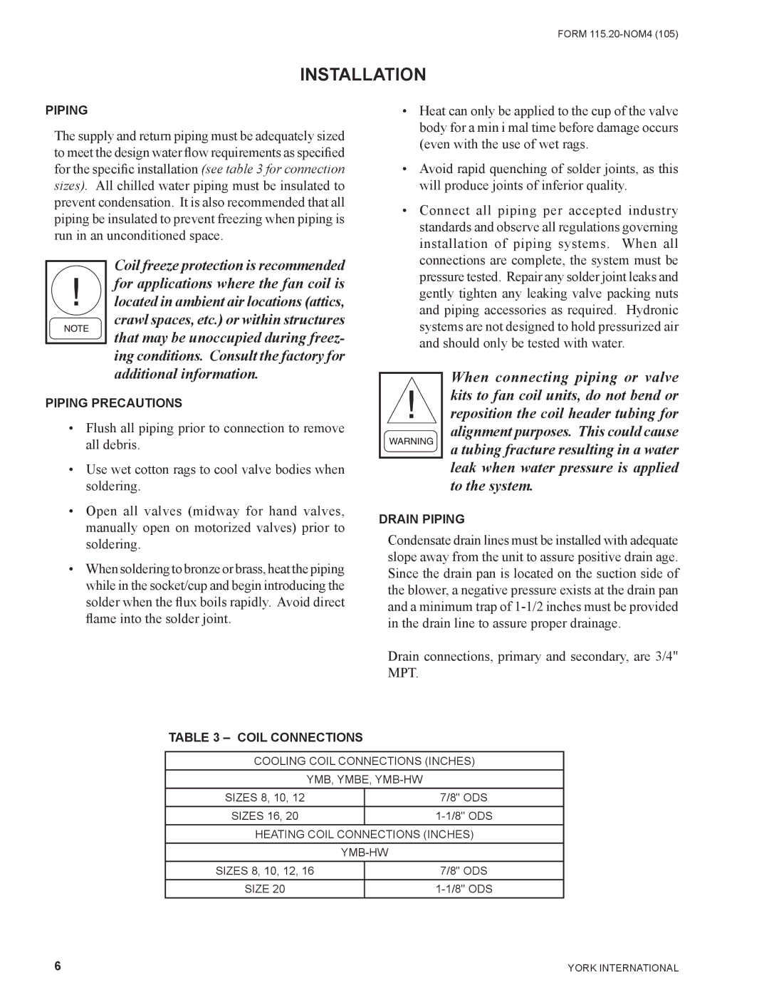
TABLE 3 – COIL CONNECTIONS

COOLING COIL CONNECTIONS (INCHES)

YMB, YMBE, YMB-HW

SIZES 8, 10, 12


7/8" ODS

SIZES 16, 20


1-1/8" ODS

HEATING COIL CONNECTIONS (INCHES)


YMB-HW

SIZES 8, 10, 12, 16


7/8" ODS

SIZE 20


1-1/8" ODS

6

YORK INTERNATIONAL

Page 6
Image 6
York YMB Drain connections, primary and secondary, are 3/4 MPT, Piping Precautions, Drain Piping, Coil Connections

YMB-HW, YMBE, YMB specifications

York YMBE, YMB-HW, and YMB are innovative products from York, a renowned brand in heating, ventilation, and air conditioning (HVAC) systems. These models are tailored to cater to diverse commercial and industrial needs, making them indispensable for climate control in large spaces.

The York YMBE series stands out for its robust design, energy efficiency, and advanced features. These units are engineered for superior thermal performance, providing consistent comfort across various environments. One key characteristic of the YMBE models is their use of advanced refrigerants, which comply with environmental regulations while ensuring optimal cooling performance. Additionally, they are equipped with variable speed compressors that enhance efficiency and reduce energy consumption, enabling significant cost savings over time.

The YMB-HW units are specifically designed for hydronic heating applications. These systems integrate seamlessly with existing hydronic infrastructure, providing efficient heating solutions. Their intelligent control systems allow for precise temperature management, ensuring a comfortable environment even in the coldest conditions. The YMB-HW models are compatible with a range of renewable energy sources, including solar and geothermal, demonstrating York's commitment to sustainability.

The original YMB series maintains a reputation for reliability and performance. These units are constructed with durable materials to withstand harsh operating conditions, making them a favorite in high-demand applications such as manufacturing, warehousing, and large retail spaces. The YMB models feature advanced filtration systems that improve indoor air quality, a crucial factor in today's focus on health and wellness.

Technologically, York products boast integrated controls that facilitate smart building management and monitoring. This feature allows facility managers to optimize energy use, leading to greater operational efficiency. Additionally, user-friendly interfaces make it easy to adjust settings, schedule operations, and receive alerts, providing peace of mind and ensuring optimal performance.

In summary, York's YMBE, YMB-HW, and YMB models represent the pinnacle of HVAC technology, combining efficiency, durability, and advanced controls. These systems not only meet the demands of modern buildings but also embrace a forward-thinking approach to sustainability, reinforcing York's position as a leader in the HVAC industry.