FORM
INSTALLATION
VALVE CLUSTER
2-Way Motorized Valve Assemblies
1.The motorized valve assembly should be attached to the supply header, which is the connection nearest the air outlet flange on the unit.
2.Prior to soldering the joints, operate all the hand valves to ensure that the handles will fully open and close without interference to other valves, ceiling, wall, plenum or other accessories.
3.All valves will operate at any angle with the excep- tion of the motorized valve, which must be installed with the power head above horizontal. The actuator box requires a 3/4" clearance for removal.
00186VIP
FIG. 4 – 2 WAY MOTORIZED VALVE ASSEMBLY
3-Way Motorized Valve Assembly
1.The
2.Prior to soldering the joints, operate all the hand valves to ensure that the handles will fully open and close without interference to other valves, ceiling, wall, plenum or other accessories.
3.All valves will operate at any angle with the excep- tion of the motorized valve, which must be installed with the power head above horizontal. The actuator box requires a 3/4" clearance for removal.
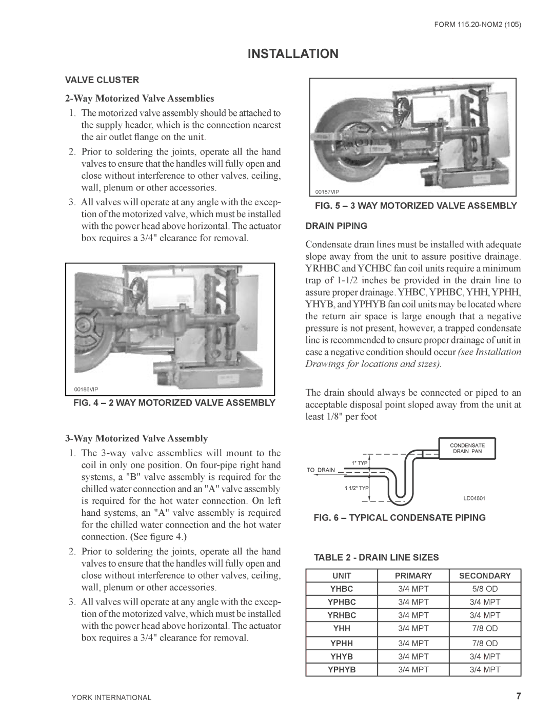
00187VIP
FIG. 5 – 3 WAY MOTORIZED VALVE ASSEMBLY
DRAIN PIPING
Condensate drain lines must be installed with adequate slope away from the unit to assure positive drainage. YRHBC and YCHBC fan coil units require a minimum trap of
The drain should always be connected or piped to an acceptable disposal point sloped away from the unit at least 1/8" per foot
LD04801
FIG. 6 – TYPICAL CONDENSATE PIPING
TABLE 2 - DRAIN LINE SIZES
UNIT | PRIMARY | SECONDARY |
YHBC | 3/4 MPT | 5/8 OD |
YPHBC | 3/4 MPT | 3/4 MPT |
YRHBC | 3/4 MPT | 3/4 MPT |
YHH | 3/4 MPT | 7/8 OD |
|
|
|
YPHH | 3/4 MPT | 7/8 OD |
YHYB | 3/4 MPT | 3/4 MPT |
YPHYB | 3/4 MPT | 3/4 MPT |
YORK INTERNATIONAL | 7 |