Stereo Mode
• Two independent amplifiers, Amp A and Amp B.
• Two loads are driven.
• Loads are connected between the BLACK and RED posts on each channel.
Bridge Mode
• Channel A & B inputs are paralleled.
• Output signals are equal in amplitude but opposite in phase.
• One load is driven.
• The load is connected between the two RED binding posts. The BLACK posts are not used.
Subsonic Filter Switch
The AP4020/4040 features a specially designed subsonic filter which effectively blocks potentially destructive energy in the band below 40 Hz. The filter provides a 12 dB/octave. skirt below 40 Hz. It is implemented with a two pole network designed to minimize phase shift down to 40 Hz. We recom- mend using this filter in conjunction with some subwoofers and with all high power full range cabinets. With the filter disabled, the AP4020/4040 is flat down to
Limiter Switch
With the internal limiters activated, the AP4020/4040’s gain is continuously adjusted to fit the signal within the avail- able dynamic range. Occasional clipping is permitted. The limiters will not only help to protect your system’s horns and tweeters, but will automatically make the best use of the avail- able dynamic headroom. With the limiters activated, all you need to do is turn up the signal level until you start to see some clipping. The limiters will make sure that you are get- ting the maximum clean power output at all times. Setting the switch to the IN position completely disables both limiters.
Protect LED
In the event of a shorted load or a load which is of too low an impedance for the amplifier to handle the PROTECT LED will flash alternately on and off at about 3 second intervals. The sound may come on and off at ½ second intervals. In this case, the fault is in the speakers or the speaker cables and should be located and remedied. No reset of the AP4020 /4040 is required to restore proper operation. The PROTECT LED will stay on if the amplifier has overheated. Check the speaker load impedance and any restrictions to air flow at the air intake or exhaust vents of the amplifier.
Short Circuit Protection
The AP4020/4040 is fully protected against all possible pas- sive load conditions. It can operate into a dead short continu- ously without damage. (However, we don’t recommend that you short your AP4020/4040 “just for fun.” Shorts do create a lot of stress on the output devices). The output stage uses a unique triple slope
DC Protection
In the unlikely event of the AP4020/4040’s outputs going DC, a thyristor circuit will short the output terminals and divert all potentially harmful currents away from your speakers.
Thermal Protection
In the unlikely event that the AP4020/4040 overheats, the sig- nal will be sporadically cut off and the PROTECT LED will stay on. The AP4020/4040 is designed and tested to operate under “worst case” conditions without shutting down, so if you experi- ence a thermal shut down you should check for blocked air flow.
Cooling
The fan draws air in from the front and expels hot air through the rear vents. This is compatible with most installa- tions. Since hot air rises, the heated air forcibly expelled from the back tends to rise away from the equipment rack. This draws cool air from the floor upwards into the front of the rack. In some cases where the rear of the rack is obstructed, it may be necessary to install rack fans to aid cooling. If there are no obstructions, no secondary cooling is required.
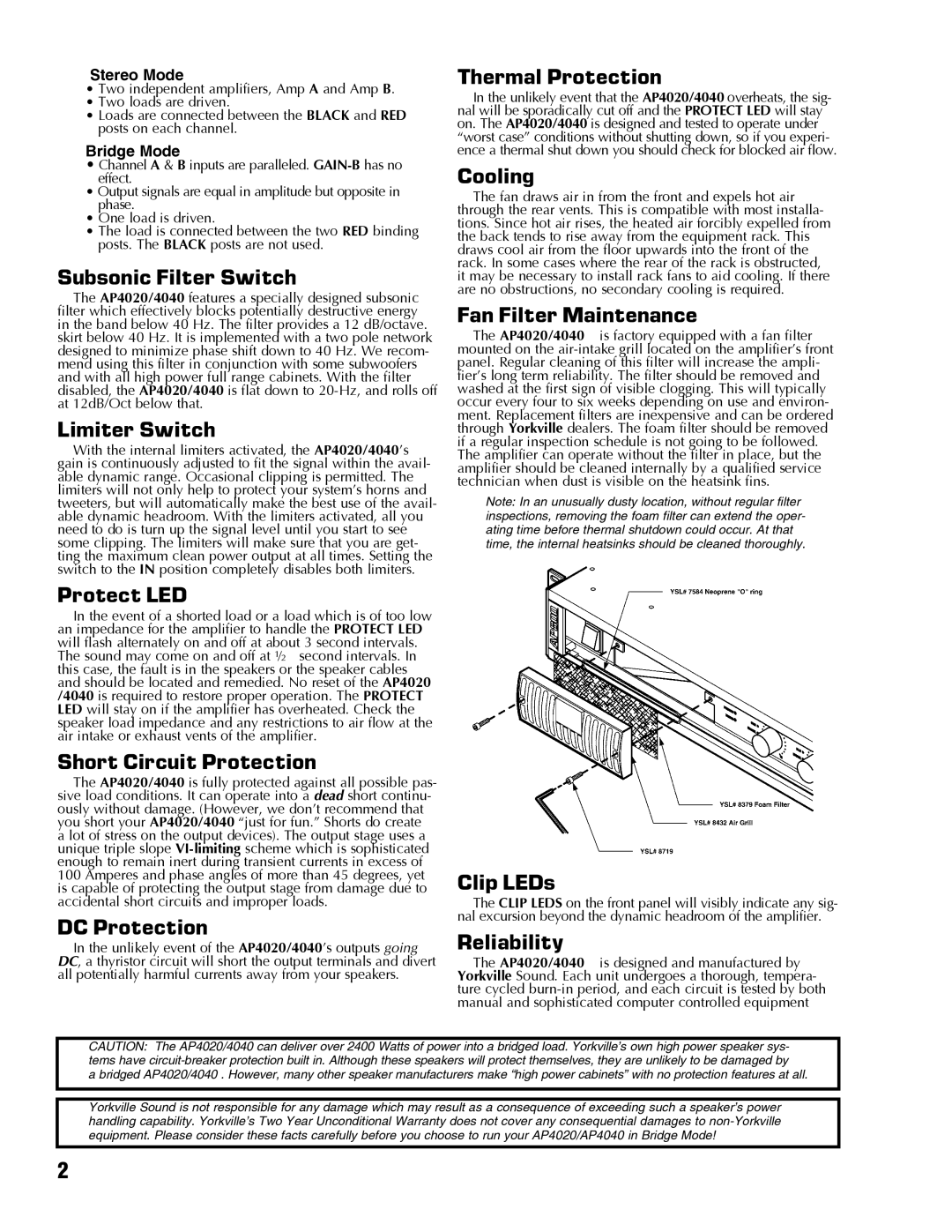
Fan Filter Maintenance
The AP4020/4040 is factory equipped with a fan filter mounted on the
Note: In an unusually dusty location, without regular filter inspections, removing the foam filter can extend the oper- ating time before thermal shutdown could occur. At that time, the internal heatsinks should be cleaned thoroughly.
Clip LEDs
The CLIP LEDS on the front panel will visibly indicate any sig- nal excursion beyond the dynamic headroom of the amplifier.
Reliability
The AP4020/4040 is designed and manufactured by Yorkville Sound. Each unit undergoes a thorough, tempera- ture cycled
CAUTION: The AP4020/4040 can deliver over 2400 Watts of power into a bridged load. Yorkville’s own high power speaker sys- tems have
a bridged AP4020/4040 . However, many other speaker manufacturers make “high power cabinets” with no protection features at all.
Yorkville Sound is not responsible for any damage which may result as a consequence of exceeding such a speaker’s power handling capability. Yorkville’s Two Year Unconditional Warranty does not cover any consequential damages to
2