which is capable of identifying any deviation from the design center parameters. The design of the AP4020/4040 is conser- vative with respect to the power handling capabilities of the output devices. The topology guarantees that thermal stress not secondary breakdown will set the limits of operation, while the computer optimized heat dissipation system insures that excessive thermal stress will not occur. Yorkville’s reputa- tion as a manufacturer of reliable equipment will be further enhanced by the AP4020/4040.
The AP4020/4040 is not only suitable for use in both heavy duty touring sound reinforcement systems but also when high headroom and low distortion are needed to fully reproduce the dynamic range and clarity of today’s CD recordings. It is built to survive grueling road conditions and constant 2 ohm (4 ohm in the AP4040) operation. Its reliability in a fixed installation running 4 or 8 ohm studio monitors is without parallel.
Output Connections
WARNING: When driven to full power in Bridge Mode.
There is more than 100Vrms appearing between the bind- ing posts. This represents a significant shock hazard and due care should be taken when making any speaker con- nections. Ensure that no strands of bare conductor are exposed after inserting the speaker wire into the hole in the side of the binding post terminals.
The AP4020/4040 has
There are two Speakon™ connectors. The Speakons™ are con- nected to the amplifier’s outputs whether the amplifier is in ste- reo, mono, or bridge modes. Each Speakon™ output connector (output A and output B) is wired in parallel with it’s respective binding posts for two channel two cable connections (figure 1).
Speakon™ output A also doubles as the A&B/Bridge connec- tor. This Speakon™ contains both channels on one connector. This is convenient when connecting one speaker to the ampli- fier in bridge mode where the speaker is connected across the positives of each amplifier output. Configure the mode switch for bridge and connect the speaker to pins +1 and +2 of the
To connect a
Power Output
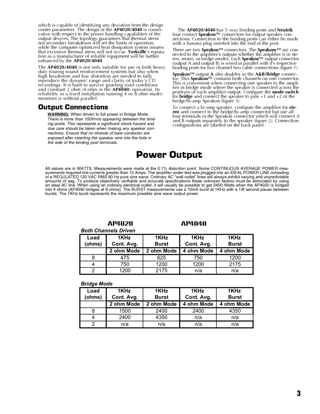
All values are in WATTS. Measurements were made at the 0.1% distortion point. Some CONTINUOUS AVERAGE POWER mea- surements required line currents greater than 15 Amps. The amplifier under test was plugged into an IDEAL POWER LINE consisting of a REGULATED 120 VAC RMS 60 Hz pure sine wave. Ordinary AC “wall outlet” lines will always exhibit varying and unpredictable amounts of sag. To produce objectively verifiable and accurate specifications these unknown factors must be eliminated by using an ideal AC line. When using an ordinary electrical outlet, it will usually be possible to get 2400 Watts when the AP4020 is bridged into 4 ohms (AP4040 bridges at 8 ohms). The BURST measurements use a 10mS burst at 1KHz with a 1/8 second pause between bursts. The 1KHz burst represents the maximum possible sine wave output power.
| AP4020 |
| AP4040 |
|
Both Channels Driven |
|
|
| |
Load | 1KHz | 1KHz | 1KHz | 1KHz |
(ohms) | Cont. Avg. | Burst | Cont. Avg. | Burst |
| 2 ohm Mode | 2 ohm Mode | 4 ohm Mode | 4 ohm Mode |
8 | 475 | 625 | 750 | 1200 |
4 | 750 | 1200 | 1200 | 2175 |
2 | 1200 | 2175 | n/a | n/a |
Bridge Mode |
|
|
| |
Load | 1KHz | 1KHz | 1KHz | 1KHz |
(ohms) | Cont. Avg. | Burst | Cont. Avg. | Burst |
| 2 ohm Mode | 2 ohm Mode | 4 ohm Mode | 4 ohm Mode |
8 | 1500 | 2400 | 2400 | 4350 |
4 | 2400 | 4350 | n/a | n/a |
2 | n/a | n/a | n/a | n/a |
3