Manuals
/
Zanussi
/
Kitchen Appliance
/
Range
Zanussi
ZGF 642
manual
Wiring Diagram, Taps Ignitor Switches Ignitor Unit
Models:
ZGF 642
1
14
18
18
Download
18 pages
28.35 Kb
11
12
13
14
15
16
17
18
Install
Wiring Diagram
Fault Finding
Warranty
Dimension
Maintenance
Symptom Solution
Procedure
To Adjust the GAS Rate
Safety
Page 14
Image 14
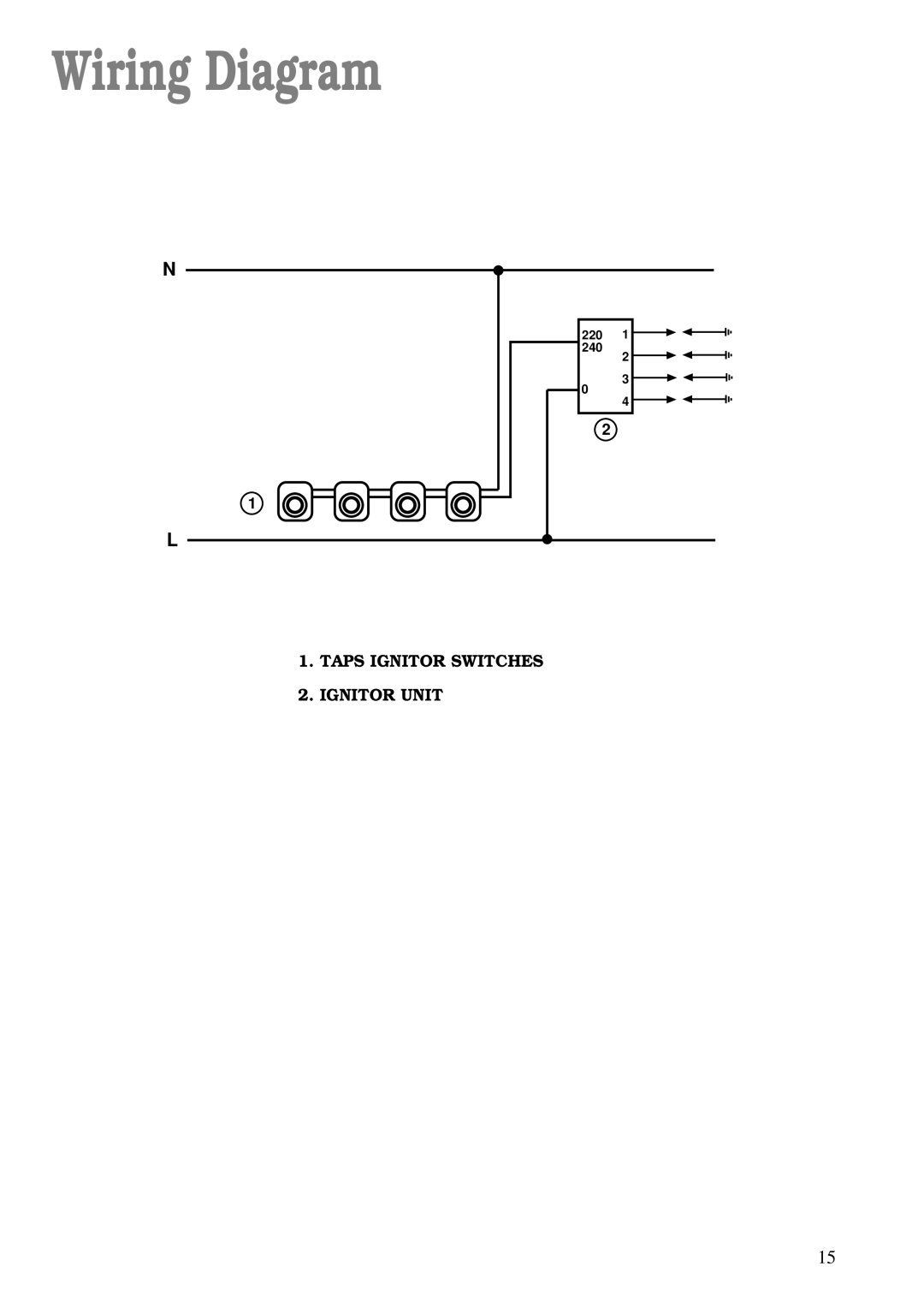
Wiring Diagram
N
1
L
220 1
240
2
3
0
4
2
1.
TAPS IGNITOR SWITCHES
2.
IGNITOR UNIT
15
Page 13
Page 15
Page 14
Image 14
Page 13
Page 15
Contents
GAS HOB Model ZGF
Service
Important Safety Information
Child Safety
During Use
Contents
Description of the Hob
Installation
When the HOB is First Installed
Hob Top
Burner Minimum Maximum
Operation
HOB Burners
Diameter
Pan Supports
Maintenance and Cleaning
HobTop
Burners
Symptom Solution
Something Not Working?
Peace of Mind for 24 Months
Service and Spare Parts
Zanussi Guarantee Conditions
Customer Care
Overall Dimensions
Instructions for the Installer
Engineer technical data
CUT OUT Dimensions
Important safety requirements
Location
Gas Connection
Installation
Dimensions are given in mm
Cut Out Size
Building
Fitting the Hob into the worktop
Electrical connections
This HOB Must be Earthed
Wiring Diagram
Taps Ignitor Switches Ignitor Unit
Earth Continuity Check
Fault Finding
Preliminary Electrical Systems Check
Ignition System / Gas Ignition
Commissioning
Procedure
Pressure Testing
To Adjust the GAS Rate
Servicing
Top
Page
Image
Contents