Disassembly/Reassembly Procedures: Disassembly Procedures — Detailed | |
|
|
7. Store Repeater Indicator Board in an
Front Panel
M6 Screws (4)
Repeater Indicator Board
Light Guide
M3 Screws (4)
Figure 5-3. Repeater Indicator Board Disassembly
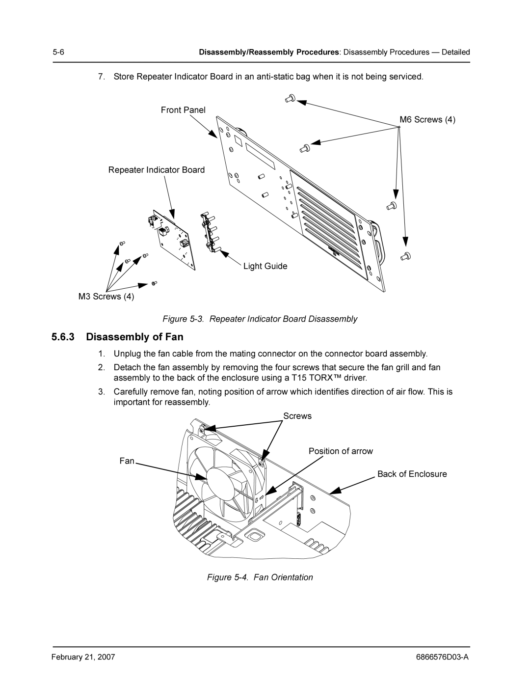
5.6.3Disassembly of Fan
1.Unplug the fan cable from the mating connector on the connector board assembly.
2.Detach the fan assembly by removing the four screws that secure the fan grill and fan assembly to the back of the enclosure using a T15 TORX™ driver.
3.Carefully remove fan, noting position of arrow which identifies direction of air flow. This is important for reassembly.
Screws
Position of arrow
Fan
Back of Enclosure
Figure 5-4. Fan Orientation
February 21, 2007 |