Disassembly/Reassembly Procedures: Transmit and Receive Radio Reassembly — Detailed | |
|
|
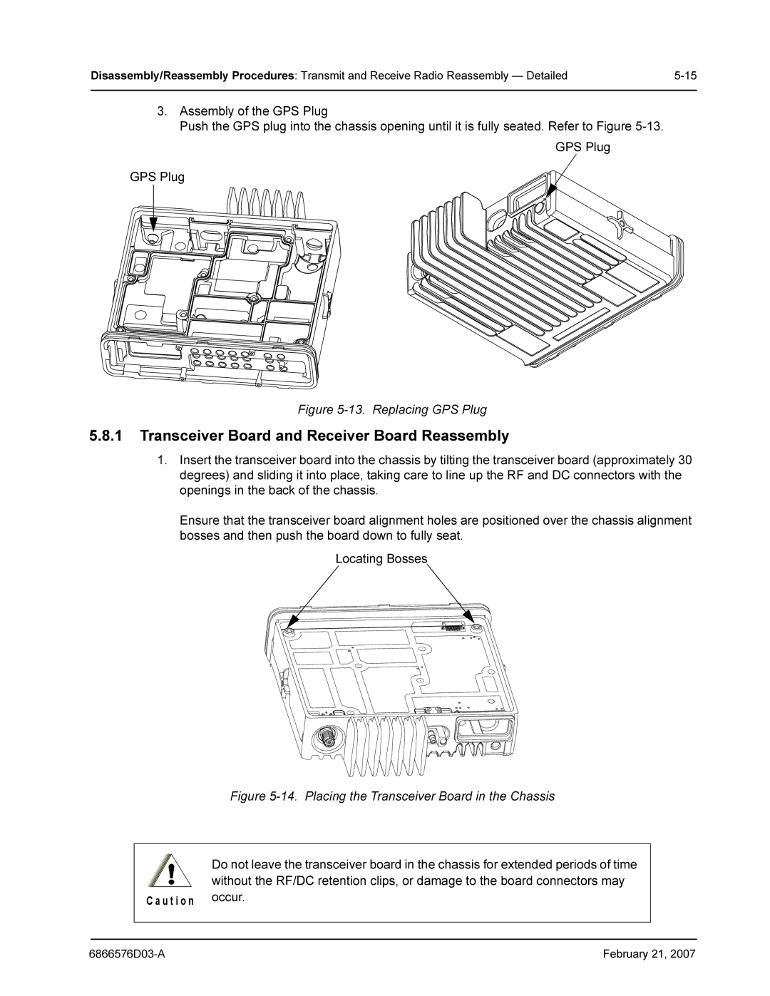
3.Assembly of the GPS Plug
Push the GPS plug into the chassis opening until it is fully seated. Refer to Figure
GPS Plug
GPS Plug
Figure 5-13. Replacing GPS Plug
5.8.1Transceiver Board and Receiver Board Reassembly
1.Insert the transceiver board into the chassis by tilting the transceiver board (approximately 30 degrees) and sliding it into place, taking care to line up the RF and DC connectors with the openings in the back of the chassis.
Ensure that the transceiver board alignment holes are positioned over the chassis alignment bosses and then push the board down to fully seat.
Locating Bosses
Figure 5-14. Placing the Transceiver Board in the Chassis
!Do not leave the transceiver board in the chassis for extended periods of time without the RF/DC retention clips, or damage to the board connectors may
| C a u t i o n | occur. |
|
|
|
|
|
|
|
|
|
February 21, 2007 |