Disassembly/Reassembly Procedures: Transmit and Receive Radio Reassembly — Detailed | |
|
|
5.8.5Reassembly of Fan
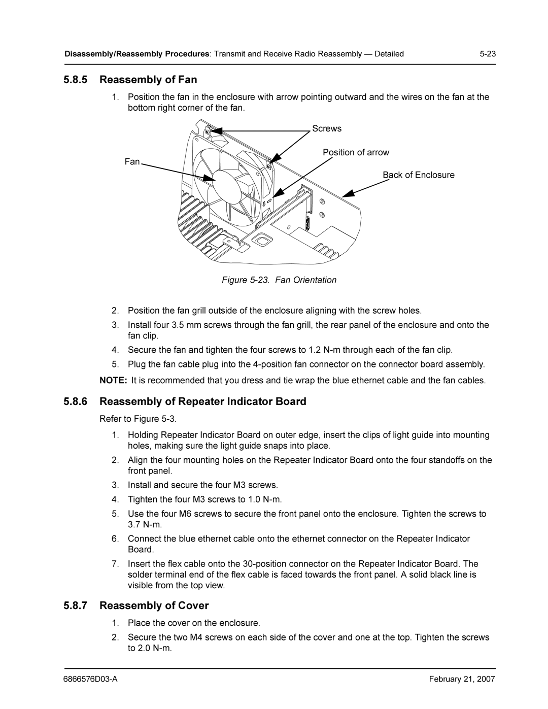
1.Position the fan in the enclosure with arrow pointing outward and the wires on the fan at the bottom right corner of the fan.
Screws
Position of arrow
Fan
Back of Enclosure
Figure 5-23. Fan Orientation
2.Position the fan grill outside of the enclosure aligning with the screw holes.
3.Install four 3.5 mm screws through the fan grill, the rear panel of the enclosure and onto the fan clip.
4.Secure the fan and tighten the four screws to 1.2 N-m through each of the fan clip.
5.Plug the fan cable plug into the 4-position fan connector on the connector board assembly.
NOTE: It is recommended that you dress and tie wrap the blue ethernet cable and the fan cables.
5.8.6Reassembly of Repeater Indicator Board
Refer to Figure
1.Holding Repeater Indicator Board on outer edge, insert the clips of light guide into mounting holes, making sure the light guide snaps into place.
2.Align the four mounting holes on the Repeater Indicator Board onto the four standoffs on the front panel.
3.Install and secure the four M3 screws.
4.Tighten the four M3 screws to 1.0
5.Use the four M6 screws to secure the front panel onto the enclosure. Tighten the screws to 3.7
6.Connect the blue ethernet cable onto the ethernet connector on the Repeater Indicator Board.
7.Insert the flex cable onto the
5.8.7Reassembly of Cover
1.Place the cover on the enclosure.
2.Secure the two M4 screws on each side of the cover and one at the top. Tighten the screws to 2.0
February 21, 2007 |
