Chapter 3 Transceiver Performance Testing
3.1General
The MOTOTRBO Repeater meets published specifications through their manufacturing process by utilizing
NOTE: Although these radios function in digital and analog modes, all testing is done in analog mode.
3.2Setup
Supply voltage is 120/240 VAC. The equipment required for alignment procedures is connected as shown in the Repeater Tuning Equipment Setup Diagram, Figure
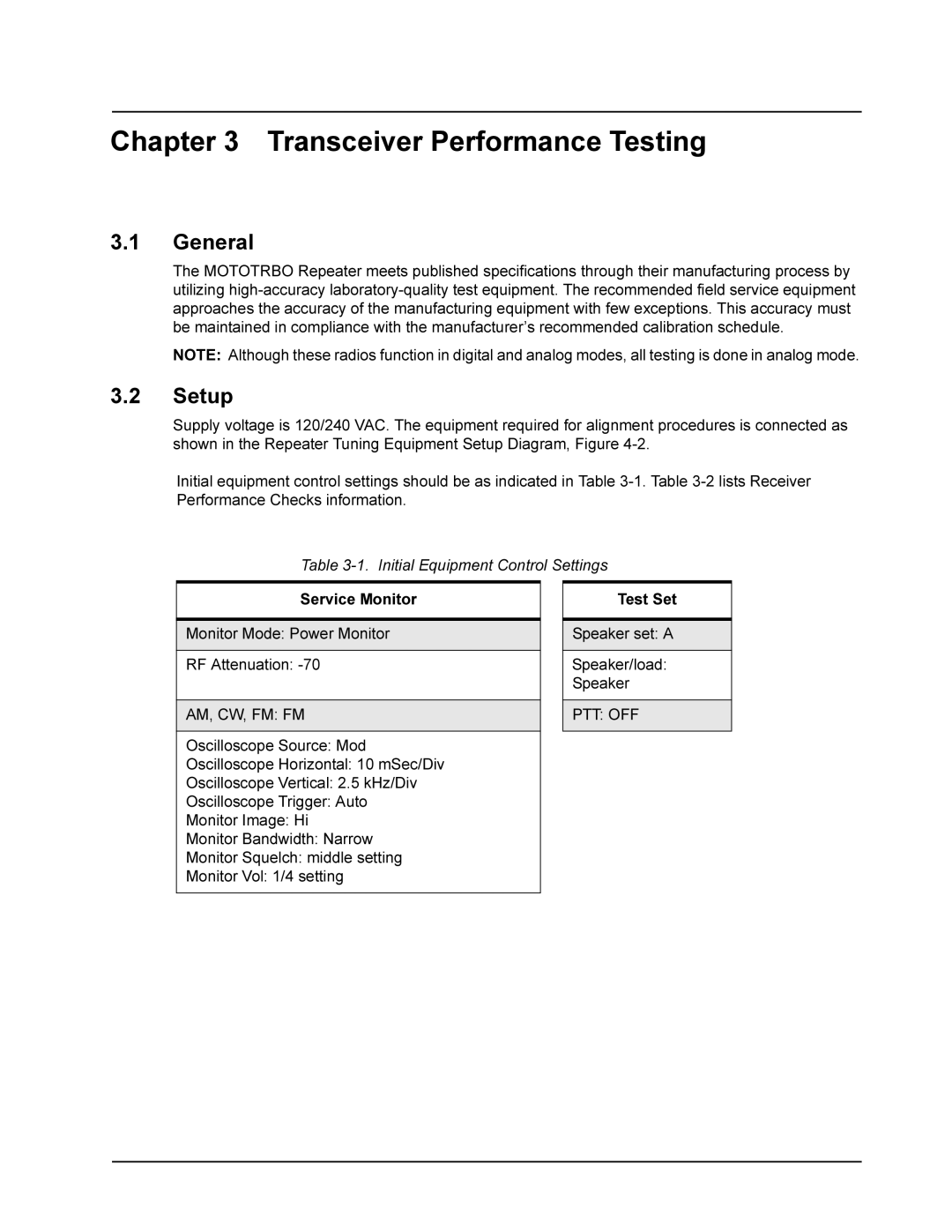
Initial equipment control settings should be as indicated in Table
Table
Service Monitor
Monitor Mode: Power Monitor
RF Attenuation:
AM, CW, FM: FM
Oscilloscope Source: Mod
Oscilloscope Horizontal: 10 mSec/Div
Oscilloscope Vertical: 2.5 kHz/Div
Oscilloscope Trigger: Auto
Monitor Image: Hi
Monitor Bandwidth: Narrow
Monitor Squelch: middle setting
Monitor Vol: 1/4 setting
Test Set
Speaker set: A
Speaker/load: Speaker