Disassembly/Reassembly Procedures: Disassembly Procedures — Detailed | |
|
|
5.6.2Disassembly of Repeater Indicator Board
(Refer to Figure
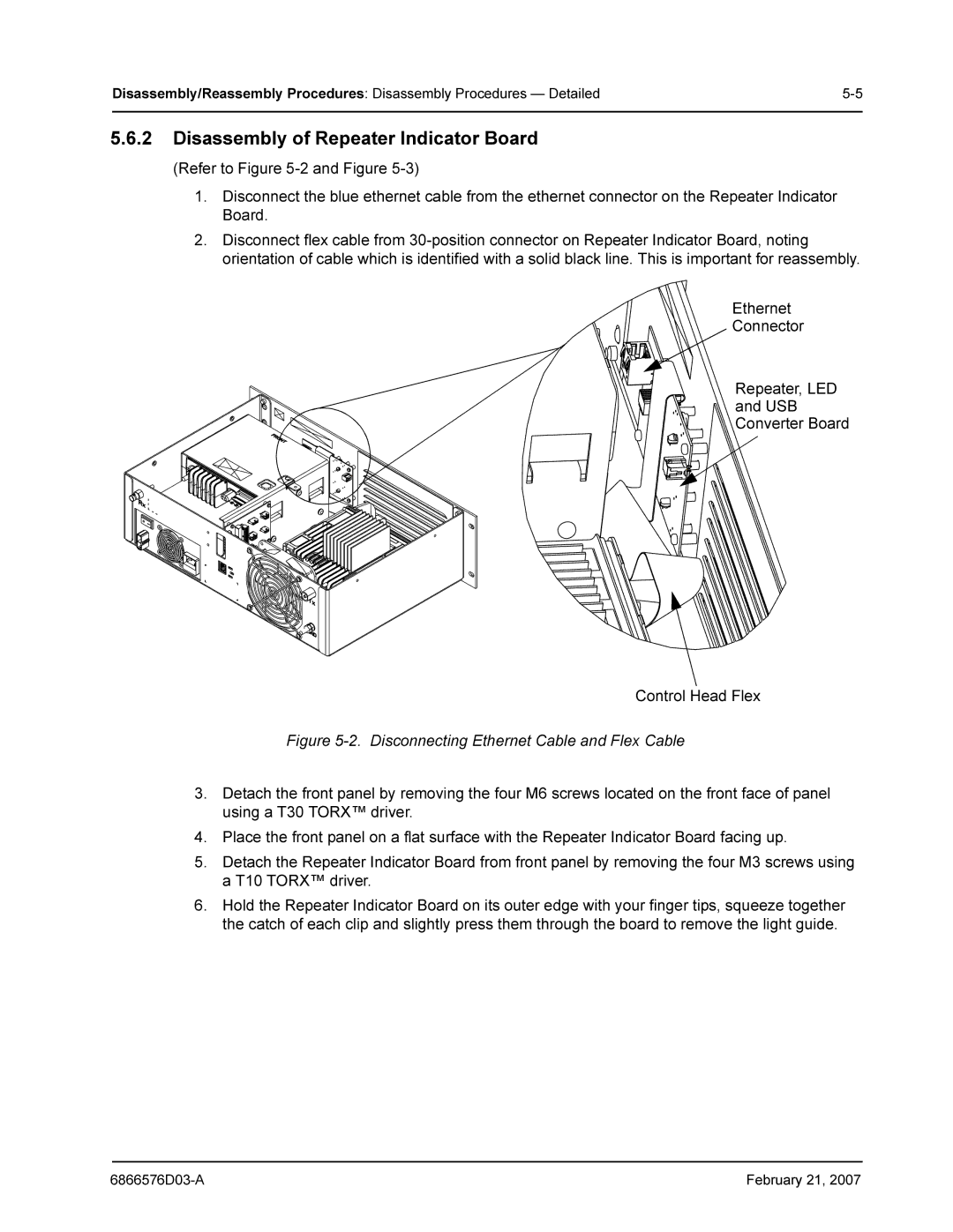
1.Disconnect the blue ethernet cable from the ethernet connector on the Repeater Indicator Board.
2.Disconnect flex cable from
Ethernet
Connector
Repeater, LED
and USB
Converter Board
Control Head Flex
Figure 5-2. Disconnecting Ethernet Cable and Flex Cable
3.Detach the front panel by removing the four M6 screws located on the front face of panel using a T30 TORX™ driver.
4.Place the front panel on a flat surface with the Repeater Indicator Board facing up.
5.Detach the Repeater Indicator Board from front panel by removing the four M3 screws using a T10 TORX™ driver.
6.Hold the Repeater Indicator Board on its outer edge with your finger tips, squeeze together the catch of each clip and slightly press them through the board to remove the light guide.
February 21, 2007 |