Connections (Continued)
Basic TV Connections
Make one of the following connections, depending on the capabilities of the equipment to be connected.
RF coaxial connection
Connect the RF.OUT jack on the DVD+VCR to the antenna in jack on the TV using the
![]() ote
ote
If you use this connection, tune the TV to the DVD+VCR’s RF output channel (CH 3 or 4).
How to set the DVD+VCR’s RF output channel
1.Set the TV to the VCR channel (3 or 4) depending upon the selected channel.
2.When the DVD+VCR is turned off, press and hold CH (V/v) on the front panel for more than five seconds.
It will turn itself on and “RF03” or “RF04” appears in the dis- play window.
3.Press CH (V/v) on the front panel or CH/TRK (v/V) on the remote control to change the RF output chan- nel (CH 03 or CH 04).
4.Turn off the DVD+VCR.
Audio/Video connection
1 | Connect the DVD/VCR VIDEO OUT jack on the |
DVD+VCR to the video in jack on the TV using the | |
| video cable supplied (V). |
2 Connect the Left and Right DVD/VCR AUDIO OUT jacks on the DVD+VCR to the audio left/right in jacks on the TV (A1) using the supplied audio cables.
![]() ote
ote
If you use this connection, set the TV’s source selector to VIDEO.
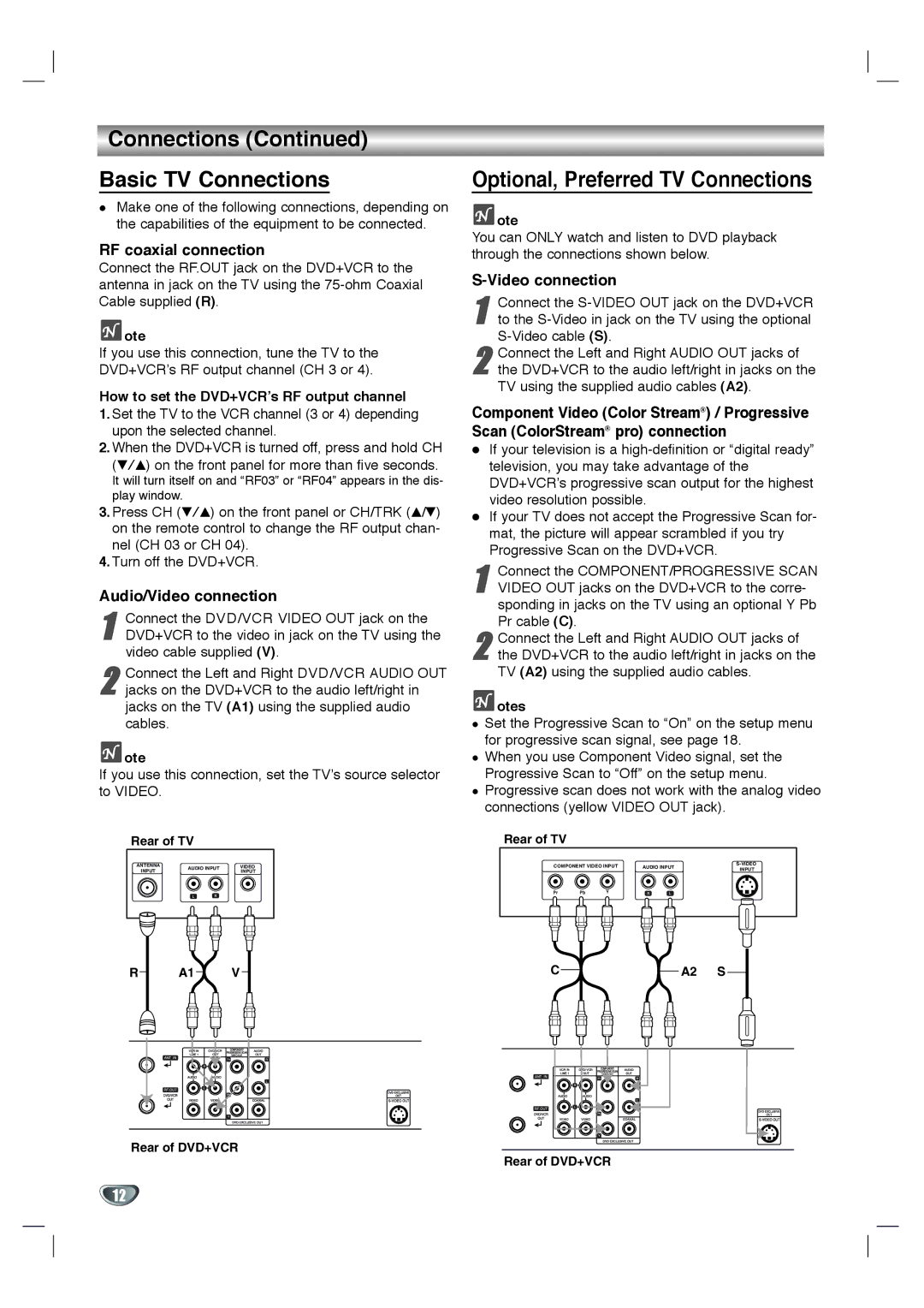
Rear of TV
ANTENNA | AUDIO INPUT | VIDEO | ||
INPUT | INPUT | |||
|
| |||
| L | R |
| |
R A1 V
Rear of DVD+VCR
Optional, Preferred TV Connections
![]() ote
ote
You can ONLY watch and listen to DVD playback through the connections shown below.
S-Video connection
1 | Connect the |
to the |
2 Connect the Left and Right AUDIO OUT jacks of the DVD+VCR to the audio left/right in jacks on the TV using the supplied audio cables (A2).
Component Video (Color Stream®) / Progressive Scan (ColorStream® pro) connection
If your television is a
If your TV does not accept the Progressive Scan for- mat, the picture will appear scrambled if you try Progressive Scan on the DVD+VCR.
1 Connect the COMPONENT/PROGRESSIVE SCAN VIDEO OUT jacks on the DVD+VCR to the corre- sponding in jacks on the TV using an optional Y Pb Pr cable (C).
2 Connect the Left and Right AUDIO OUT jacks of the DVD+VCR to the audio left/right in jacks on the TV (A2) using the supplied audio cables.
 otes
otes
Set the Progressive Scan to “On” on the setup menu for progressive scan signal, see page 18.
When you use Component Video signal, set the Progressive Scan to “Off” on the setup menu. Progressive scan does not work with the analog video connections (yellow VIDEO OUT jack).
Rear of TV
COMPONENT VIDEO INPUT | AUDIO INPUT | |||||
INPUT | ||||||
|
|
|
|
| ||
Pr | Pb | Y | R | L |
| |
C | A2 S |
Rear of DVD+VCR
12