Ryobi RY52004 manual Position for Starting, Starting and Stopping, See Figures 10

Page 12

OPERATION

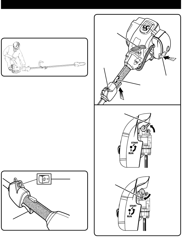
POSITION FOR STARTING

See Figure 9.

Lay the pruner on the ground and ensure that no objects or obstructions are in the immediate vicinity. Make sure nothing can come in contact with the bar and chain.

Fig. 9

STARTER

GRIP

ENGINE

SWITCH

PRIMER BULB

STARTING AND STOPPING

See Figures 10 - 12.

TO START A COLD ENGINE:

DO NOT squeeze the throttle trigger until the engine starts and runs.

n Lay the trimmer on a flat, bare surface. n PRIME - Press the primer bulb 7 times. n SET the start lever to the START position.

TRIGGER

LOCK

THROTTLE TRIGGER

START LEVER

Fig. 11

n PULL the rope until the engine starts. n Allow the engine to run for 15 seconds. n Squeeze trigger lock and throttle trigger.

NOTE: Squeezing the throttle trigger releases the start lever to the RUN position.

TO START A WARM ENGINE:

PULL the rope until the engine starts.

TO STOP THE ENGINE:

Press and hold the switch in the stop “ ” position until the engine stops.

ENGINE

SWITCH

TRIGGER

LOCK

THROTTLE


TRIGGER

Fig. 10


START

POSITION

START LEVER

RUN POSITION

Fig. 12

12

Image 12
Contents OPERATOR’S Manual Save this Manual for Future ReferenceTable of Contents IntroductionGeneral Safety Rules Read ALL InstructionsSpecific Safety Rules RefuelingSymbols Symbol Name DESIGNATION/EXPLANATIONService Product Specifications Engine SwitchKnow Your Pruner Barrier HandleAssembly Installing the Shoulder StrapUnpacking Packing ListConnecting the Power Head to the Pruner Attachment Chain OilerFueling and Refueling the Pruner Premium Exact MIXOperation Preparation for CuttingSee Figures 5 Limbing and Pruning Cutting GuideSee Figures 8 MaximumPosition for Starting Starting and StoppingSee Figures 10 Maintenance General MaintenanceChain Tension See Figures 13Replacing the BAR See Figures 15Chain BAR BAR NUT BAR NUT Chain Tensioning ScrewIdle Speed Adjustment Idle Speed ScrewChain Oiler Tank Replace CAP Remove Chain Maintenance HOW to Sharpen the CuttersSee Figures 24 Cleaning the Exhaust Port and Muffler Replacing and Cleaning AIR FilterSpark Arrestor See Figures 28Fuel CAP Spark PlugStorage 1 Month or Longer Troubleshooting Problem Cause RemedyWarranty Limited Warranty StatementMANUFACTURER’S Warranty Coverage OWNER’S Warranty ResponsibilitiesMaintenance Requirements CoverageThis Product WAS Manufactured with a Catalyst Muffler Page Service Model NO. and Serial no California Proposition