MAINTENANCE
REPLACING THE BAR
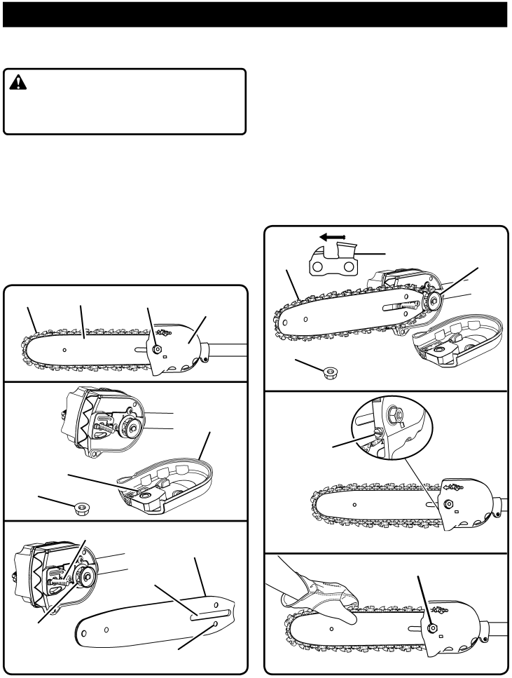
See Figures 15 - 20.
WARNING:
To avoid possible serious injury, stop engine before re- placing the bar, chain, or performing any maintenance operation.
nRemove the bar nut and drivecase cover.
nThe bar contains a bar stud slot that fits over the bar stud. The bar also contains a chain tensioning pin hole which fits over the chain tensioning pin.
nPlace the bar onto the bar stud so that the chain tension- ing pin fits into the chain tensioning pin hole.
nFit the chain over the sprocket and into the bar groove. The cutters on the top of the bar should face toward the bar tip, in the direction of the chain rotation.
nReplace the side case cover and install the bar nut. Tighten the bar nut finger tight only. The bar must be free to move for tension adjustment.
CHAIN | BAR | BAR NUT | DRIVECASE |
|
|
| COVER |
Fig. 15
DRIVECASE
COVER
CHAIN
TENSIONING PIN
BAR NUT
Fig. 16
BAR STUD
BAR
BAR STUD SLOT
SPROCKET
CHAIN TENSIONING |
|
PIN HOLE | Fig. 17 |
nRemove all slack from chain by turning the chain tension- ing screw clockwise, assuring that the chain seats into the bar groove during tensioning.
nLift the tip of the bar up to check for sag. Release the tip of the bar, and turn the chain tensioning screw 1/2 turn clockwise. Repeat this process until sag does not exist.
nHold the tip of the bar up and tighten the bar nut se- curely.
nChain is correctly tensioned when there is no slack on the underside of the bar, the chain is snug, but it can be turned by hand without binding.
NOTE: If chain is too tight, it will not rotate. Loosen the bar nut slightly and turn adjusting screw 1/4 turn counter- clockwise. Lift the tip of the bar up and retighten bar nut.
CHAIN | CHAIN ROTATION SPROCKET |
BAR NUT
Fig. 18
CHAIN
TENSIONING SCREW
Fig. 19
BAR NUT
Fig. 20
14