Snapper 3314520BVE, 281320BE, 301320BE, 331520KVE PRE-START Check List

Page 6

Section 2 - OPERATING INSTRUCTIONS

2.1PRE-START CHECK LIST

Make the following checks and perform the service required before each start-up.

2.1.1.Check tires and add or release air as needed to bring pressure to 12 psi in front and 12 psi in rear tires.

2.1.2.Check guards, deflectors and covers to make sure all are in place and securely tightened.

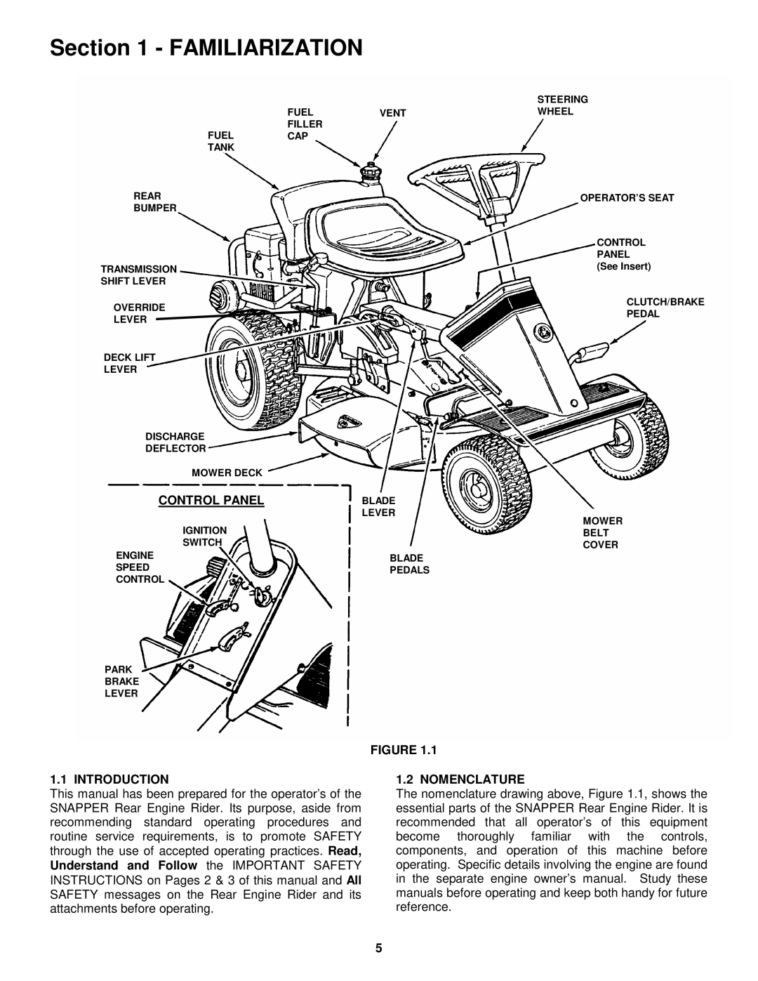
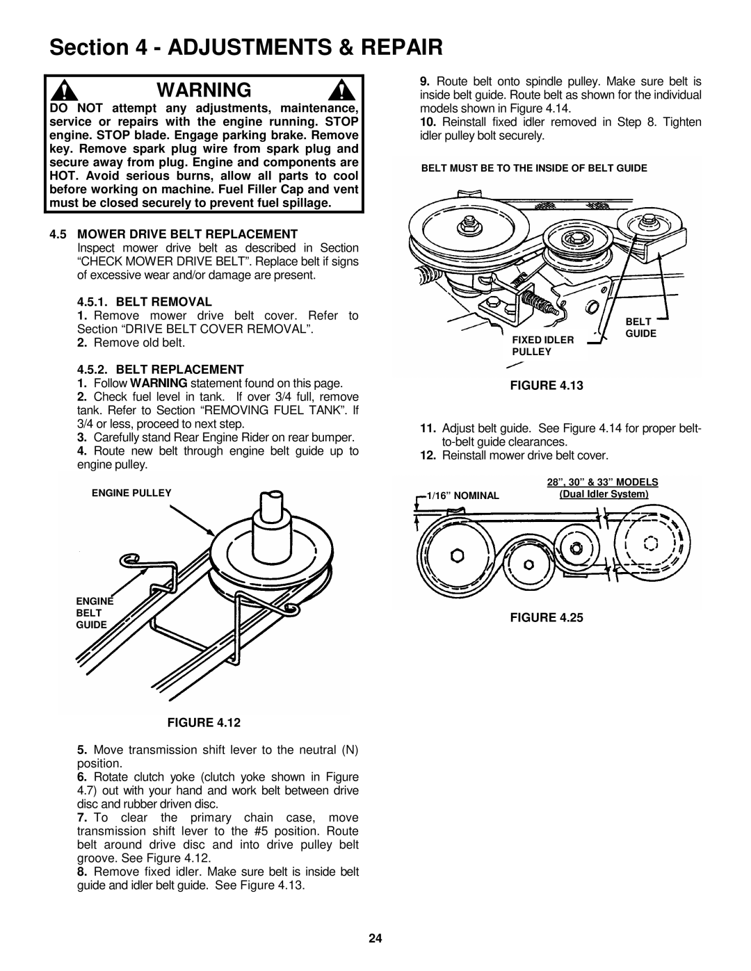
2.1.3.Check engine oil and add oil as needed to bring level up to the FULL mark. Refer to engine owner’s manual for oil specifications. See Figure 2.1.

SAFE LEVEL

AREA

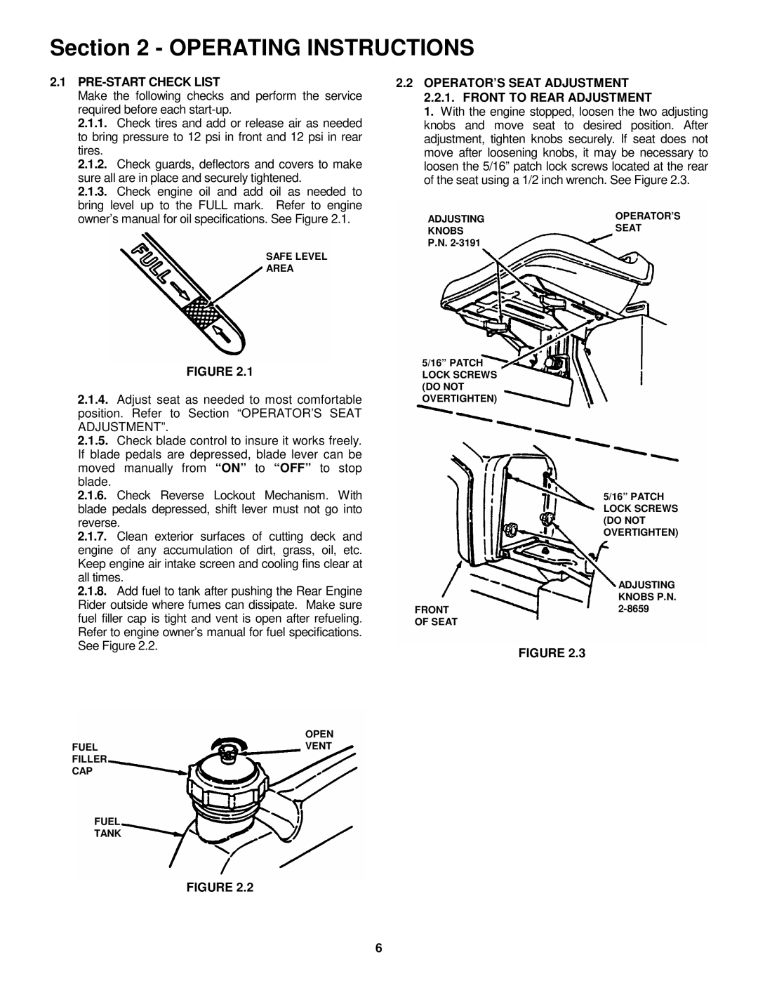
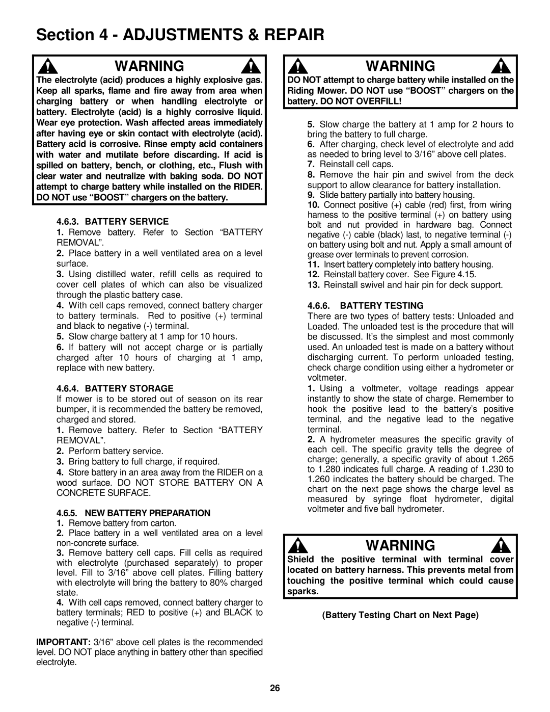
2.2 OPERATOR’S SEAT ADJUSTMENT 2.2.1. FRONT TO REAR ADJUSTMENT

1.With the engine stopped, loosen the two adjusting knobs and move seat to desired position. After adjustment, tighten knobs securely. If seat does not move after loosening knobs, it may be necessary to loosen the 5/16” patch lock screws located at the rear of the seat using a 1/2 inch wrench. See Figure 2.3.

ADJUSTING

OPERATOR’S

KNOBS

SEAT

P.N. 2-3191


FIGURE 2.1

2.1.4.Adjust seat as needed to most comfortable position. Refer to Section “OPERATOR’S SEAT ADJUSTMENT”.

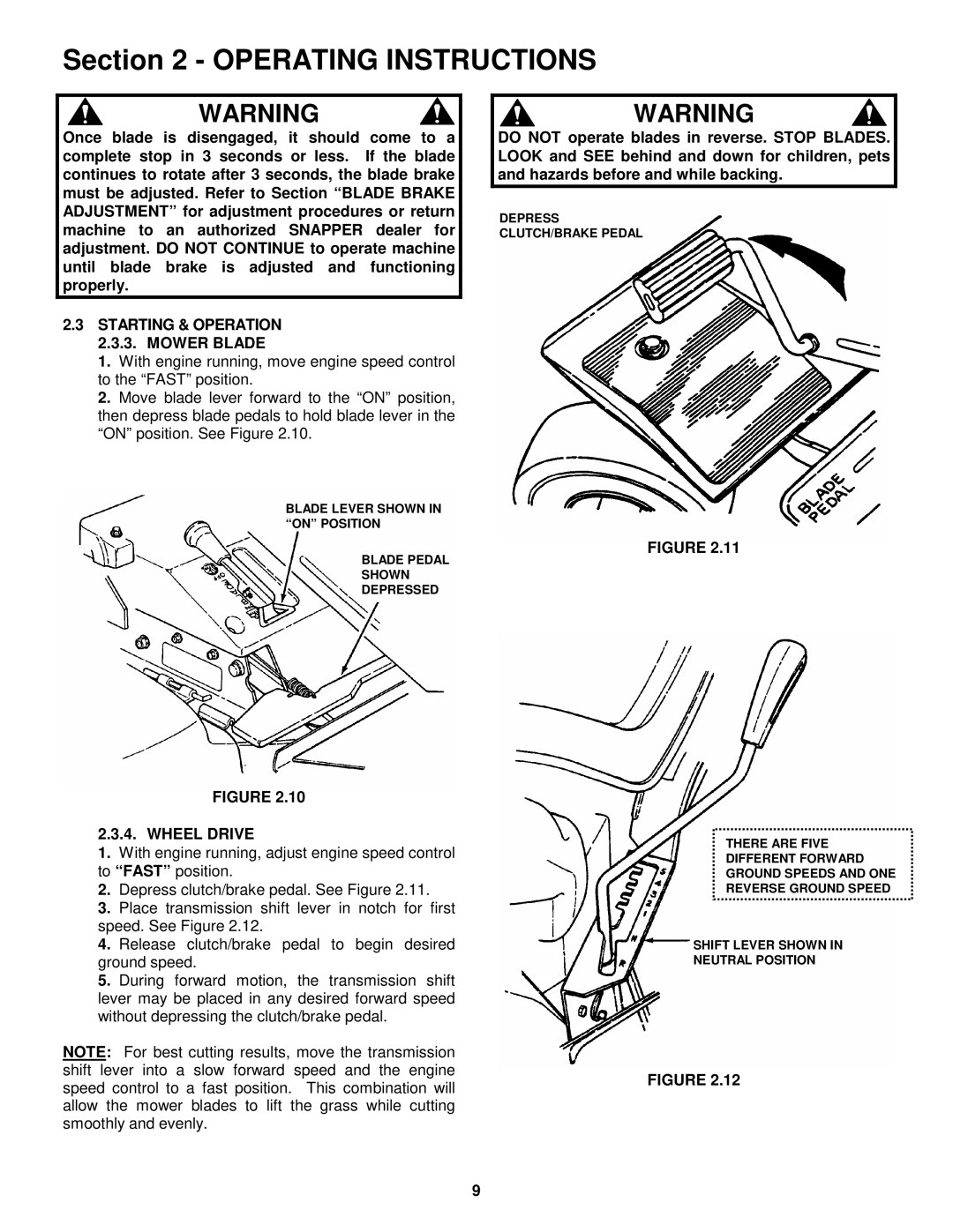
2.1.5.Check blade control to insure it works freely. If blade pedals are depressed, blade lever can be moved manually from “ON” to “OFF” to stop blade.

2.1.6.Check Reverse Lockout Mechanism. With blade pedals depressed, shift lever must not go into reverse.

2.1.7.Clean exterior surfaces of cutting deck and engine of any accumulation of dirt, grass, oil, etc. Keep engine air intake screen and cooling fins clear at all times.

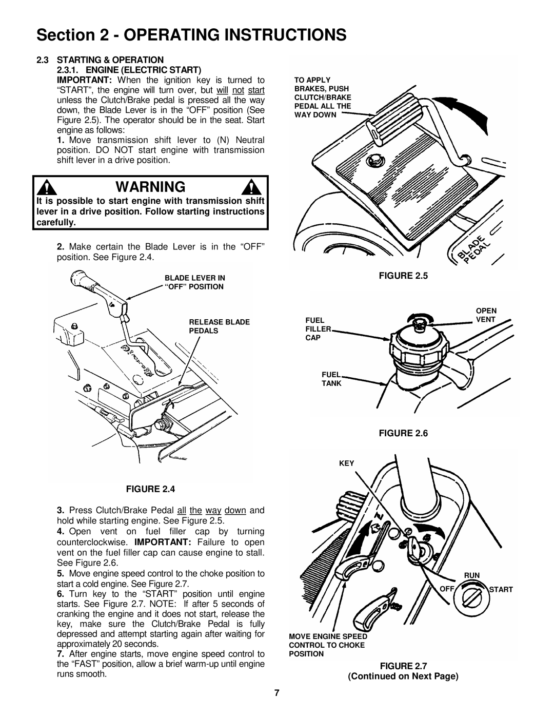
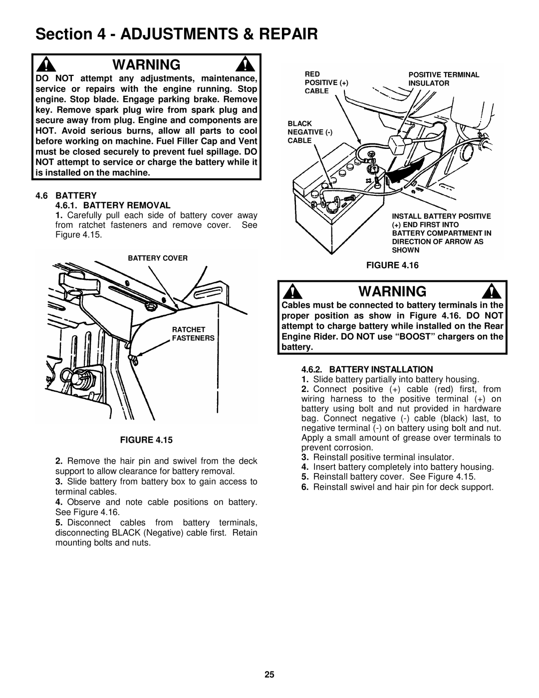
2.1.8.Add fuel to tank after pushing the Rear Engine Rider outside where fumes can dissipate. Make sure fuel filler cap is tight and vent is open after refueling. Refer to engine owner’s manual for fuel specifications. See Figure 2.2.

5/16” PATCH LOCK SCREWS (DO NOT OVERTIGHTEN)

5/16” PATCH LOCK SCREWS (DO NOT OVERTIGHTEN)

ADJUSTING

KNOBS P.N.

FRONT2-8659

OF SEAT

FIGURE 2.3

OPEN

FUELVENT FILLER

CAP

FUEL

TANK

FIGURE 2.2

6

Image 6
Contents Rear Engine Riding Mower Series Manual No -3542 I.R /29/00Important Safety Instructions Operation Table of Contents Control Panel IntroductionNomenclature OPERATOR’S Seat Adjustment 2.2.1. Front to Rear Adjustment PRE-START Check ListStarting & Operation Engine Electric Start On NextStarting & Operation Engine Electric StartEngine Manual Start Starting & Operation 2.3.3. Mower Blade Wheel DriveStopping ENGINE, Wheel DRIVE, Blade 2.4.1. Engine Mower BladeCutting Height Adjustment Stopping ENGINE, Wheel DRIVE, Blade 2.4.4. Park BrakeDo not park machine on slopes Reverse Lockout Mechanism Reverse Lockout Mechanism OverrideService After First 5 Hours Service Engine AIR Cleaner Check Mower BladeChange Engine OIL Blade Brake Service After First 5 Hours 3.2.4. Check Blade Drive BeltService Brake / Park Brake Interlock SystemClean Mower Deck Service Every 25 Operating HoursBattery Fluid Level Lubrication Grease FittingsFront Wheel Bearing Lubrication Rear Axle Bearing LubricationFuel Filter Service AnnuallyEngine Every TWO YearsRemoving Fuel Tank Engine Adjustments & Repair Blade Brake AdjustmentMower Deck & Component Adjustments Mower Deck Adjustment Front to Rear Levelness 28, & 33 DecksFront to Rear Levelness 30 Decks Wheel Brake Adjustment Brake Cable Chain Case Loosen JAM Nuts Mower Blade Replacement 4.4.1. Blade Wear Limits Blade SharpeningBelt Removal Mower Drive Belt ReplacementBelt Replacement Beltfigure 4.25 GuideBattery Battery Removal Battery InstallationNEW Battery Preparation 1. Remove battery from carton Battery ServiceBattery Storage Battery TestingSnapper Rear Engine Rider Accessories Problem Probable Cause Corrective Action StopCutting Grass Loss Of TractionBlades Not Cutting ImproperlySubject Service Reference To be Performed PagesMAINTENANCE/REPLACEMENT Parts Maintenance Parts Year Limited Warranty Disclaimer of WarrantyPrimary Maintenance Primary Maintenance Primary Maintenance Primary Maintenance Service Notes Rear Engine Riding Mower Series