Intel D845EPI manual Power Connectors, Fan Headers, Chassis Intrusion

Page 19

Desktop Board Features

Power Connectors

The desktop board has two power connectors. See Figure 11 on page 36 for the location of the power connectors.

Fan Headers

The desktop board has two chassis fan headers and one processor fan header. See Figure 11 on page 36 for the location of the fan headers.

Chassis Intrusion

The board supports a chassis security feature that detects if the chassis cover has been removed. The security feature uses a mechanical switch (not included) on the chassis that can be connected to the chassis intrusion header on the desktop board. See Figure 11 on page 36 for the location of the chassis intrusion header.

Suspend to RAM (Instantly Available PC Technology)

CAUTION

For Instantly Available PC technology, the 5 V standby line for the power supply must be capable of delivering adequate +5 V standby current. Failure to provide adequate standby current when using this feature can damage the power supply and/or effect ACPI S3 sleep state functionality.

Instantly Available PC technology enables the board to enter the ACPI S3 (Suspend-to-RAM) sleep state. While in the S3 sleep state, the computer will appear to be off. When signaled by a wake-up device or event, the system quickly returns to its last known awake state.

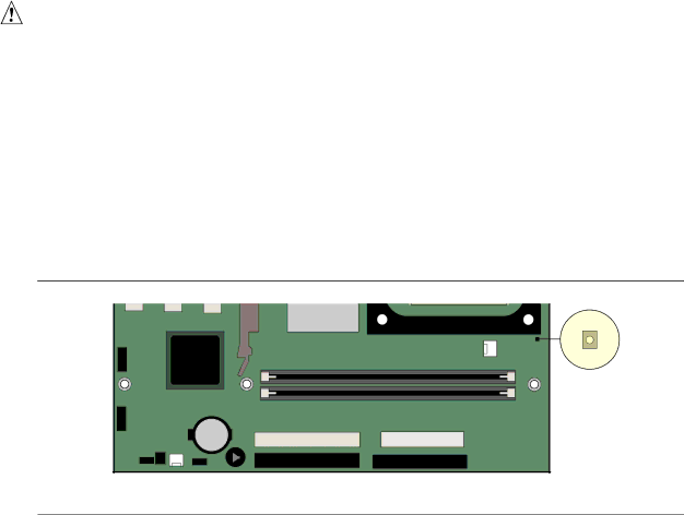
The desktop board’s standby power indicator, shown in Figure 2, is lit when there is standby power to the system. This includes the memory modules and PCI bus connectors, even when the computer appears to be off.

If the system has a dual-colored power LED on the front panel, the sleep state is indicated by the LED turning amber.

OM16287

Figure 2. Location of Standby Power Indicator

19

Image 19
Contents Intel Desktop Board D845EPI Product Guide Revision History Following conventions are used in this manual PrefaceTerminology Contents Desktop Board Resources Regulatory Compliance ContentsTables Power Management Desktop Board FeaturesDescribes the major features of Intel Desktop Board D845EPI Feature SummarySupported Operating Systems Desktop Board Components Desktop Board FeaturesItem Description Related LinksDesignation GHz ProcessorProcessors Supported by the Desktop Board TypeSystem Bus MHz Main MemoryMemory Support Memory SpeedAudio Subsystem Intel 845E ChipsetAccelerated Graphics Port AGP RJ-45 LAN Connector LEDsRJ-45 LAN Connector LEDs LAN Subsystem OptionalExpansion Slots PCI Auto ConfigurationHi-Speed USB 2.0 Support Enhanced IDE InterfaceIDE Auto Configuration Power Management FeaturesSecurity Passwords Suspend to RAM Instantly Available PC Technology Power ConnectorsFan Headers Chassis IntrusionSpeaker BatteryReal-Time Clock Before You Begin Installing and Replacing Desktop Board ComponentsInstallation Instructions Installation PrecautionsEnsure Electromagnetic Compatibility EMC Compliance Chassis and Component Certifications Prevent Power Supply OverloadPlace Battery Marking Installing and Replacing Desktop Board ComponentsUse Only for Intended Applications Installing the I/O ShieldDesktop Board Mounting Screw Holes Installing and Removing the Desktop BoardInstalling a Processor Installing and Removing a ProcessorInstalling the Processor Fan Heatsink Removing a Processor Connecting the Processor Fan Heatsink CableInstalling DIMMs Installing and Removing MemoryRemoving DIMMs Installing an AGP Card Installing and Removing an AGP CardRemoving the AGP Card Connecting the IDE Cable Connecting the IDE Cable Internal Headers Connecting Internal HeadersShows the pin assignments for the front panel audio header Installing a Front Panel Audio SolutionFront Panel Audio Header Signal Names J8A1 Pin Signal NameUSB 2.0 Header J9F2 Connecting the Front Panel HeaderInstalling a USB 2.0 Solution Front Panel Header J9G1Location of Hardware Control and Power Connectors Connecting Hardware Control and Power CablesConnecting Power Cables Connecting Hardware Control CablesShows the add-in card and peripheral interface connectors Connecting Add-In Card and Peripheral Interface ConnectorsJumper Settings for the Bios Setup Program Modes J9H2 Setting the Bios Configuration Jumper BlockJumper Setting Mode Clearing Passwords Shows the back panel connectors Back Panel Connectors$87,21 Replacing the Battery$9957,0172 $$6 Removing the Battery from the Desktop Board Intel Desktop Board D845EPI Product Guide Updating the Bios with the Intel Iflash Bios Update Utility Updating the BiosObtaining the Bios Update File Recovering the Bios Updating the BiosTurn on the computer and continue with the Bios update see Power cordUpdating the Bios Intel Desktop Board D845EPI Product Guide Shows the Bios Setup program menu bar Using the Bios Setup ProgramBios Setup Program Menu Bar Shows the function keys available for menu screens Maintenance MenuBios Setup Program Function Keys Maintenance MenuMain Menu Using the Bios Setup ProgramEnglish default Main MenuAdvanced Menu MaintenanceSecurity Power Boot Exit Feature OptionsOptions Auto default Description PCI Configuration SubmenuPCI Configuration Submenu PCI ConfigurationOptions No default Boot Configuration SubmenuBoot Configuration Submenu Boot ConfigurationIRQ 4 default Peripheral Configuration SubmenuPeripheral Configuration Submenu Auto default 3F8 defaultEnabled default Description Bi-directional defaultDefault IRQ 7 defaultBoth default IDE Configuration SubmenuIDE Configuration Submenu IDE ConfigurationPrimary/Secondary IDE Master/Slave Submenus Sectors default DescriptionPrimary/Secondary IDE Master/Slave Submenus Options Auto default Disabled default 44 MB 3½ default Diskette Configuration SubmenuDiskette Configuration Submenu Diskette ConfigurationEvent Log Configuration Submenu Event Log Configuration SubmenuEvent Log Configuration Video Configuration Video Configuration SubmenuSubmenu shown in is used to configure video features Video Configuration SubmenuUSB Configuration USB Configuration SubmenuMenu shown in is used to configure USB features USB Configuration SubmenuOptions Enabled default Chipset Configuration SubmenuChipset Configuration Submenu Chipset ConfigurationOptions Auto default Security Menu If no password entered previously FeatureYes default Full defaultLast State default Power MenuMenu shown in is used to set power management features Power MenuAcpi Submenu Submenu represented in is for setting the Acpi featuresAdvanced Configuration and Power Interface Acpi SubmenuBoot Menu Boot MenuMain Advanced Security Power Options Description Boot Device Priority SubmenuSubmenu represented in is for setting boot devices priority Boot Device Priority SubmenuOptions Description Submenu shown in is for setting hard disk drivesHard Disk Drives Submenu Hard Disk Drives SubmenuRemovable Devices Submenu Submenu in shown is for setting removable devicesRemovable Devices Submenu Atapi CD-ROM Drives Submenu shown in is for setting Atapi CD-ROM drivesAtapi CD-ROM Drives Submenu Exit Menu Feature DescriptionExit Menu System Memory Map Desktop Board ResourcesMemory Map DMA ChannelsInterrupts InterruptsNumber of Beeps Description Error Messages and IndicatorsBios Beep Codes Beep CodesExplanation Bios Error MessagesBios Error Messages Error MessageError Messages and Indicators Intel Desktop Board D845EPI Product Guide European Union Declaration of Conformity Statement Safety RegulationsSafety Regulations Regulatory ComplianceDisposal Considerations Product Ecology StatementsRecycling Considerations EMC Regulations EMC RegulationsRegulatory Compliance Product Certification Markings Product Certification Markings Board LevelDescription Mark