Lexmark 500n manual Fusing unit

Page 55

5023-110

Fusing unit

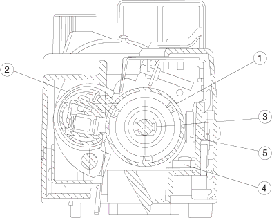
The fusing unit utilizes a thermal fusing system that contains a heated fusing roller and a belt-like backup roller. The heated roller contains an inner heating element. The backup roller contains three pressure members located behind the belt. Paper carrying a toner image passes between the rollers where heat and pressure are applied to the paper to fuse the toner to the paper.

The fusing unit consists of the following components:

No.

Part

Function


1

Fusing roller

Used for fusing, containing a heater.


2

Back-up roller

Pressure roller.


3

Fusing heater

Heating device heated by a halogen lamp.


4

Thermistor

Sensor that detects the temperature of the fuser roller’s surface.


5

Thermal fuse

Protective device that prevents the fuser roller from being excessively


heated.


General information 1-33

Image 55
Contents Lexmark C500n 5023-110 United States Government Rights 12G9663Table of contents Diagnostic information Diagnostic aids Locations and connectors Vii 5023-110 Laser advisory label Laser noticesClass 1 Laser statement label Laser Laser noticeAvvertenze sui prodotti laser Avis relatif à l’utilisation de laserAvisos sobre el láser Lasermeddelelse LaserinformatieLaser-notis Huomautus laserlaitteestaAvís sobre el Làser Laser-meldingJapanese laser notice Chinese laser notice Korean laser notice 5023-110 Consignes de sécurité Safety informationNorme di sicurezza Pautas de Seguridad SicherheitshinweiseInformações de Segurança Informació de Seguretat Conventions PrefaceTools required for service Maintenance approachSerial number Acronyms Physical specifications and weight SpecificationsResolution Technical specificationsTime to first print Packaging and shipping dimensionsOperating clearances Print speed and performanceDuty cycle Paper and media specificationsPrinter memory Media input types and weights Output capacity by media and source Media sizesMedia guidelines Labels PaperEnvelopes TransparenciesConnectivity Standard Interfaces Internal Print ServersEnvironment Power and electrical specificationsPrinter identification Printer theory of operation Printer paper path Basic principles of color printing Printer systems descriptionMechanical and electrical structures Printer component systems Basic process of color printing Print system and transfer system Structure of OPC belt photo developer cartridge Basic structure of the print system CBV DBV Charging process Details of the print systemExposing process CBV Developing processTransfer belt Aluminum drum tube Film transfer belt First transfer drum processBelt discharge erase lamp process Belt cleaning process5023-110 Second transfer paper process Details of the transfer system Transfer belt cleaning process Description Details of the optical systemPart Function Details of the paper transportation systemFusing unit Fusing process Electrical system and function Control system structureControl of print process Print sequence diagram Laser drive control circuit 5023-110