Devices
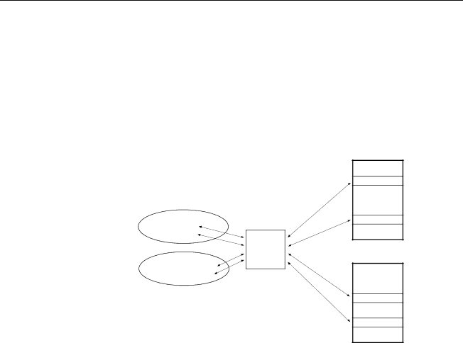
The data read by these devices is stored in registers, which are special, defined spots in the device’s memory. A list of these registers and their contents is called a register map. Figure 3 is an illustration of a register map. A client sends a request to the Server for data from a particular device. The Server knows the register map of the device and requests the register block containing the requested data.
DDE client application
Current Phase A: ___
Voltage Phase A: ___
PMCS
DDE Server
DDE client application
Ground Fault Trips Count: ___
Number of Operations: ___
Figure 3. Sample register map.
POWER LEADER EPM
Register Map
.
.
1010
.
.
.
.
1076
.
.
Enhanced MicroVersaTrip
Register Map
.
.
.
.
1056
.
.
1061
.
.
The register maps for each device are programmed into the PMCS DDE Server. The Server is then able to transform a client application’s request for “kilowatt hours at North_Meter” into a request sent to that specific device for the contents of a specific register; the client doesn’t need to know which register contains what information, merely what information is needed from which device. The PMCS DDE Server takes care of the details, and after a request for data has been placed, the Server continues to monitor that data from the particular device, updating the client application with any changes to the data.
The register maps of the POWER LEADERTM family of devices and a variety of other devices are
DDE Server User’s Guide | Chapter Two - Overview • 9 |