DeviceNet Communication Adapter
1.3Status Indicators
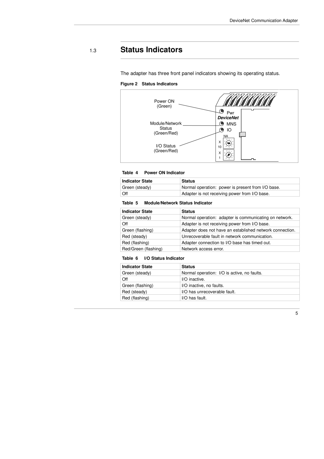
The adapter has three front panel indicators showing its operating status.
Figure 2 Status Indicators
| Power ON |
|
|
|
|
|
|
|
| |
|
|
|
|
|
|
|
|
| ||
| (Green) |
|
|
|
|
|
|
|
| |
|
|
|
|
| Pwr |
|
|
|
| |
|
|
|
| DeviceNet |
|
|
|
| ||
| Module/Network |
|
| MNS |
|
|
|
| ||
| Status |
|
| IO |
|
|
|
| ||
| (Green/Red) |
|
|
|
|
|
| |||
|
|
| NA |
|
|
|
| |||
|
|
|
|
|
|
|
|
| ||
| I/O Status |
| X |
|
|
|
|
|
| |
| 10 |
|
|
|
|
|
| |||
| (Green/Red) |
| X |
|
|
|
|
|
| |
|
|
|
|
|
|
|
| |||
|
|
|
|
|
|
|
|
|
| |
|
|
| 1 |
|
|
|
|
|
| |
|
|
|
|
|
|
|
|
| ||
|
|
|
|
|
|
|
|
|
|
|
|
|
|
|
|
|
|
|
|
|
|
|
|
|
|
|
|
|
|
|
|
|
Table 4 | Power ON Indicator |
| ||||||||
|
|
|
| |||||||
Indicator State |
| Status |
| |||||||
Green (steady) |
| Normal operation: power is present from I/O base. |
| |||||||
Off |
|
| Adapter is not receiving power from I/O base. |
| ||||||
Table 5 | Module/Network Status Indicator |
| ||||||||
|
|
| ||||||||
Indicator State |
| Status |
| |||||||
Green (steady) |
| Normal operation: adapter is communicating on network. |
| |||||||
Off |
|
| Adapter is not receiving power from I/O base. |
| ||||||
Green (flashing) |
| Adapter does not have an established network connection. |
| |||||||
Red (steady) |
| Unrecoverable fault in network communication. |
| |||||||
Red (flashing) |
| Adapter connection to I/O base has timed out. |
| |||||||
Red/Green (flashing) |
| Network access error. |
| |||||||
Table 6 | I/O Status Indicator |
| ||||||||
|
|
| ||||||||
Indicator State |
| Status |
| |||||||
Green (steady) |
| Normal operation: I/O is active, no faults. |
| |||||||
Off |
|
| I/O inactive. |
| ||||||
Green (flashing) |
| I/O inactive, no faults. |
| |||||||
Red (steady) |
| I/O has unrecoverable fault. |
| |||||||
Red (flashing) |
| I/O has fault. |
| |||||||
5
