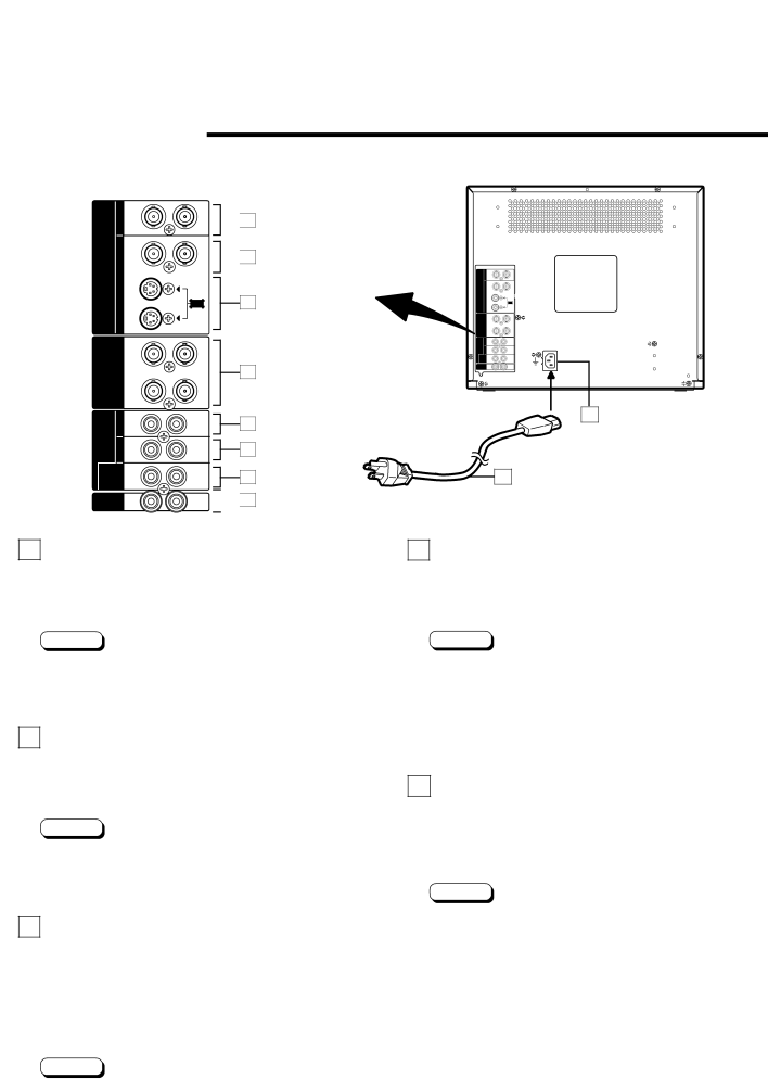
REAR VIEW
<Rear Panel>
A | IN | OUT |
| IN | OUT |
VIDEO
B IN
Y/C |
OUT
| Y/G | ||
|
| /B | |
RGB / |
|
| |
COMPO. |
|
| |
| RGB | ||
| SYNC | /R | |
A | IN | OUT | |
AUDIO B | IN | OUT | |
RGB / | IN | OUT | |
COMPO. | |||
|
| ||
REMOTE INPUT | ASPECT | ||
| A/B |
| |
![]() 20
20
![]() 21
21
| A | IN | OUT |
|
| IN | OUT |
| VIDEO |
|
|
22 | B | IN |
|
| OUT | Y/C | |
|
| Y/G | |
|
|
| /B |
| RGB/ |
|
|
| COMPO. |
|
|
|
| RGB | |
|
| SYNC | /R |
| A | IN | OUT |
| AUDIO B | IN | OUT |
| RGB/ | IN | OUT |
| COMPO. |
|
|
23 | REMOTE A/B | ASPECT | |
| INPUT |
| |
|
|
| |
24 | 28 |
To AC outlet | |
25 | (120 V AC, 50/60 Hz) |
| |
26 | 29 |
![]()
![]() 27
27
20 Video A terminals [VIDEO A IN/OUT]
Video signal input (IN) and output (OUT) terminals. The output terminal is
IN : Video signal input terminal
OUT :
23 RGB/COMPO. terminals
Input terminals for analog RGB/Y,
*The RGB SYNC input terminal is for the external synchronization (composite synchronization) signal when an analog RGB signal is input.
Notes:
*For corresponding audio signals, use the AUDIO A terminals r.
*Also refer to BASIC CONNECTION EXAMPLE on page 13.
21 Video B terminals [VIDEO B IN/OUT]
Video signal input (IN) and output (OUT) terminals. The output terminal is
IN : Video signal input terminal
OUT :
Notes:
*For corresponding audio signals, use the AUDIO B terminals t.
*Also refer to BASIC CONNECTION EXAMPLE on page 13.
22 Video B (Y/C) terminals [VIDEO B Y/C IN/ OUT]
Y/C
The output terminal is
IN :
OUT :
Notes:
Notes:
For corresponding audio signals, use the AUDIO RGB/ COMPO. terminal y.
When an analog RGB signal is input, be sure to input the external synchronization signal to the RGB SYNC terminal.
Also refer to BASIC CONNECTION EXAMPLE on page 14.
24 Audio A terminal [AUDIO A IN/OUT]
Input (IN) and output (OUT) terminals for the audio signal corresponding to the VIDEO A terminals ). The output terminal is
IN : Audio signal input terminal
OUT :
Notes:
*For corresponding video signals, use the VIDEO A terminal ).
*Also refer to BASIC CONNECTION EXAMPLE on page 13.
*For corresponding audio signals, use the AUDIO B terminals t.
*Also refer to BASIC CONNECTION EXAMPLE on page 14.
5