Allied Telesis x600-24Ts-POE manual Starting a Local Management Session

Page 87

Starting a Local

Management

Session

x600 Layer 3 Gigabit Ethernet Switch Installation Guide

3.Connect the other end of the power cord to an appropriate AC power outlet. For power specifications for the switch, refer to “Power Specifications” on page 103.

4.Start a local management session on the unit by performing the next procedure.

The following procedure describes how to connect an RJ-45 cable to an x600 switch. For information about how to log onto the AlliedPlusTM Operating System Software, see the AlliedWare Plus Operating System Software Reference Guide.

To start a local management session on the unit, perform the following procedure:
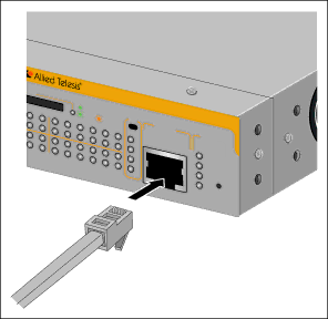
1.Connect the RJ-45 end of the management cable included with the x600 switch to the Terminal Port on the front panel of the switch, as shown in Figure 47.

SD


x600-


9


READY

24Ts/XP

Layer

3

Gig


11


abit E


13


thernet


15


BUSY


Swi


17

FAULT

SFP


tch


19

CONSOLE


21R

23R

L/A


STATUS


21


10

12

14


22


FAULT


16


23


18


20


22R


MASTER


24R

24


RPS


PWR

RESET


1320

Figure 47. Connecting the Management Cable to the RJ-45 Terminal Port

on the Switch

2.Connect the other end of the cable to an RS-232 port on a terminal or a personal computer with a terminal emulation program.

87

Image 87
Contents Installation Guide Page Electrical Safety and Emissions Standards Translated Safety Statements Contents 100 106 Contents SD Card List of FiguresFigures List of Tables Tables Preface Product Documentation Starting a Management Session Symbol Meaning Description Safety Symbols Used in this DocumentWhere to Find Web-based Guides Contacting Allied Telesis Management Software UpdatesChapter OverviewIntroduction LEDs Switch DescriptionsShows the x600-24Ts/XP switch front and rear panel X600-24Ts/XP SwitchShows the x600-48Ts switch front and rear panel X600-44Ts/XP X600-48Ts/XP SwitchX600-24Ts-POE Switch 10/100/1000Base-T Ports Connector Type Speed Duplex Mode Maximum DistanceCable Type Auto-MDI/ MDI-X Port Pinouts SFP Transceiver Slots XFP Transceiver Slots Models Ports and Slots Combo PortsSD Card Slot 10/100/1000 Base-T LEDs Port LEDsLED LINK/ACT LEDs XFP Transceiver Slot LEDs SFP LEDs x600-48 Port Switch SFP Slot LED DescriptionsState Description System Status LEDsStack LEDs Non PoE Switch Stack LEDsMstr Secure Digital Slot LED Secure Digital SD LEDTerminal Port Power Over Ethernet Maximum Power Class Page AT-RPS3204 Redundant Power Supply Unit Redundant Power SuppliesAT-LBM Loop Back Module VCS Stacking Module AC Power Connector Overview Virtual Chassis Stacking VCStackTM Introduction Features of VCStacking Physical StackVCS Stacking Modules, Cables, and Connections Ring Configuration VCStack Recovery StatesEvent on Master Node Reaction on Reaction on Stack Resiliency Link Configurations via Switch Ports Resilient Stacked Topology Role of the Stack Master Stack FormationCommon Stack Configuration Stack Member Identification Stack Member Failure Recovery Fallback Action VCS Failure RecoveryStack Maintenance Virtual Chassis Stacking Installing the Hardware Reviewing Safety Precautions X600 Layer 3 Gigabit Ethernet Switch Installation Guide Installing the Hardware Unpacking a Switch Installing the Power Cord Retaining Clip Actactivity Installing the Switches in an Equipment RackMounting the Switch in a Rack 24Ts/XP Resetting the SwitchVC Stacking Module Installation Installing AT-StackXG Module Securing the AT-StackXG Stacking Module Software Reference Installing the Hardware Cabling the Network Ports Twisted Pair Cable Specifications Twisted Pair and Fiber Optic SpecificationsSFP/XFP Installing an SFP Transceiver Installing SFP/XFP Transceivers1331 1334 Installing an XFP Transceiver Installing an XFP TransceiverCabling the Network Ports Cabling the 10/100/1000Base-T and Fiber Optic Ports Connecting the AC Power Cord Powering on a SwitchStarting a Local Management Session Cabling the Network Ports Warranty Registration Cabling the Network Ports Troubleshooting Power LED is Off Twisted Pair Port Link LED is Off SFP or XFP LED is Off Transceiver is Installed but the Status is Not Present System Fault LED is Blinking System Fault LED is Steadily On Cannot Establish a Local Out-of-Band Management Session Switch Functions Intermittently Issues with Virtual Stacking Chassis Configuration Appendix a Technical SpecificationsPhysical Specifications Environmental Specifications102 Certifications Power SpecificationsRJ-45 Twisted Pair Port Pinouts Pin SignalPinout Pair RJ-45 Style Serial Terminal Port Pinouts AT-RPS3104 17-pin Connector PinoutsPin Definition AT-RPS3204 21-pin D-combo Port and Connector Pinouts Pin Appendix a Technical Specifications 110
Related manuals
Manual 112 pages 51.04 Kb