In some instruments such as some models of |
| |
2 | ||
ADI series, instead of having a connector, there |
| |
is a cable gland with a cable with three colours |
| |
(brown, blue and green/yellow). In this case the |
| |
| ||
connections should be made as follows: |
| |
Green/yellow | = Earth |
|
Brown | = + |
|
Blue | = - |
|
MAINTENANCE
1. Change of the vane position respect the limit switch
3 |
| Sin conexión |
| ||
| ||
|
| No connection |
1
_ (Blue)azul) + (marrón)(Brown) Tierra Earth
AMD-MAXIMUM
Place the limit switch indicator in the required scale value, fixing it by means of the 2 screws. After that, move manually the shaft that supports the indicator needle, until the indicator needle coincides with the maximum limit switch indicator. After that, loosen the grub screw (1.5
mmAllen key) of the vane and make point 1 coincide with the centre of the detector ( Figure 3 ).
Tighten the screw to fix the vane.
AMD-MINIMUM
![]() 2 1
2 1
Figure 3
![]() 1 2
1 2
Figure 4
The process is the same as for the maximum point, but making the point 2 coincide with the centre of the detector ( Figure 4 ).
In the event that the instrument has two limit switches, the working range will be limited to the following values:
From 0 to 25% of the scale, for the AMD of the minimum limit switch. From 75 to 100% of the scale, for the AMD of the maximum limit switch.
2. Electrical verification of the limit switch
a)Check that the voltage at the terminals 1 and 2 is over 7.5 V when the vane is in the slot. Connect a multimeter with the scale in DC mA, in series with the terminal 2.
b)Verify that the current is less than 1 mA when the vane is in the slot, and more than 3 mA when the vane is out of the slot.
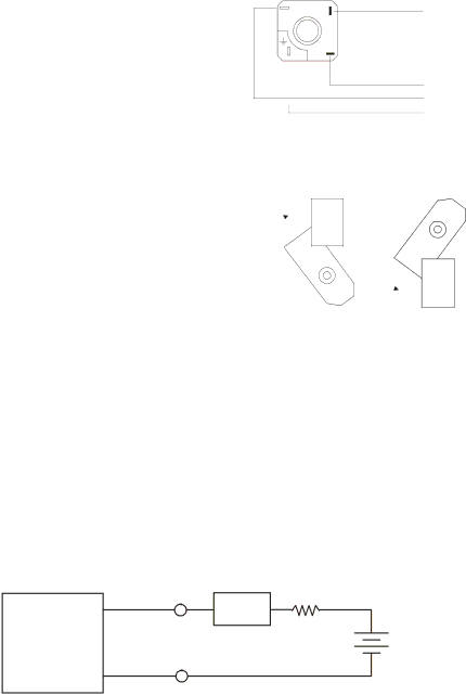
If you don’t have the NAMUR amplifier, the current can be checked using the following circuit diagram:
2 | Multimeter |
| 1 kΩ | |
+ |
| + | ||
mA | + | |||
- | ||||
|
|
| ||
AMD |
|
|
| |
1 |
|
| - | |
- |
|
| ||
|
|
|
9V Battery
(8.2V Nominal for
NAMUR )
If you don’t have the detector, the operation of the amplifier can be checked using the following circuit diagram:
3