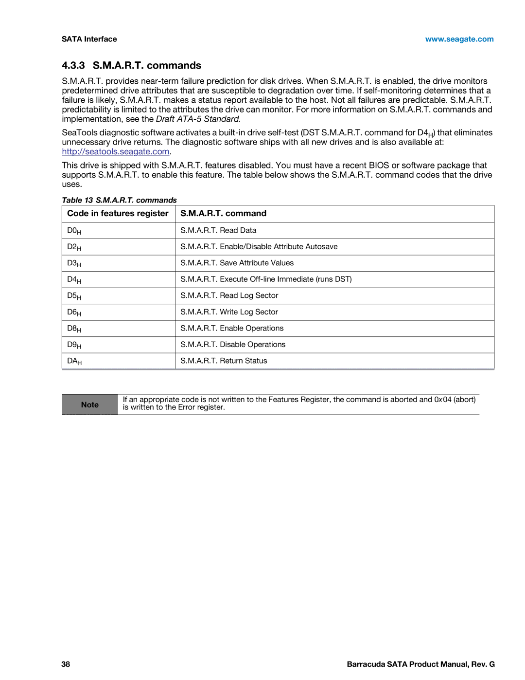
Seagate STBD2000101, STBD3000100, ST1000DM003, ST2000DM001 Set Features command, 0AH, 0BH, 0CH, Aah

Page 37

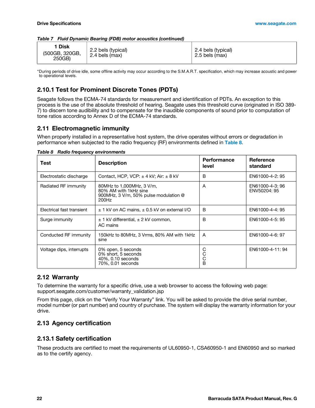
www.seagate.com

SATA Interface

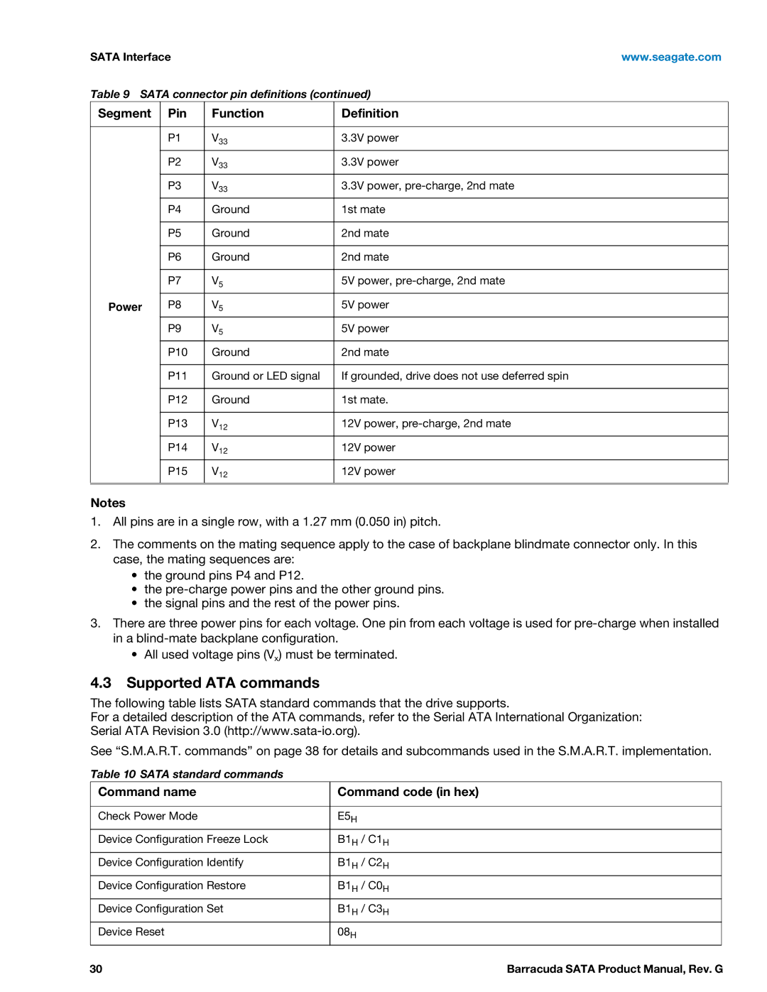
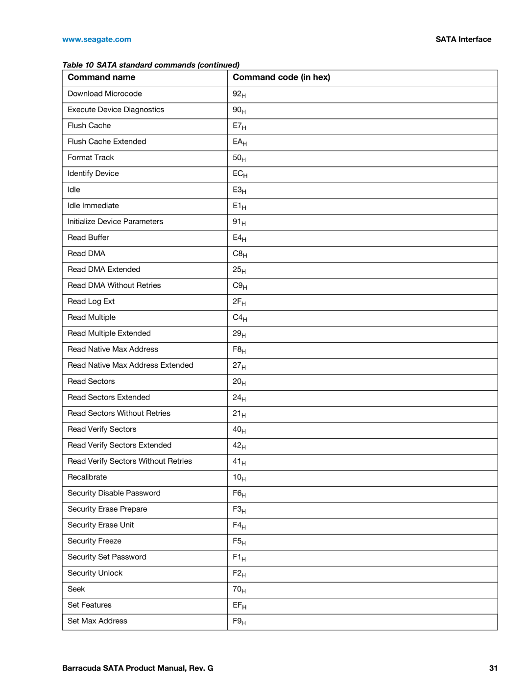
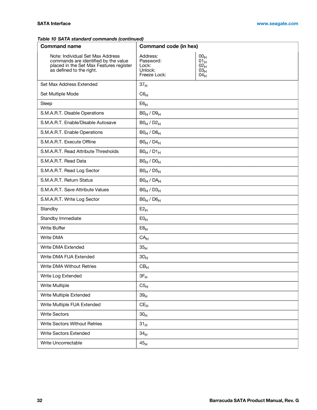
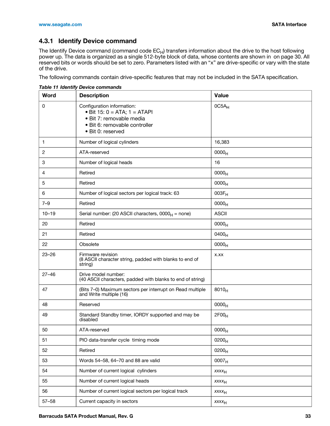
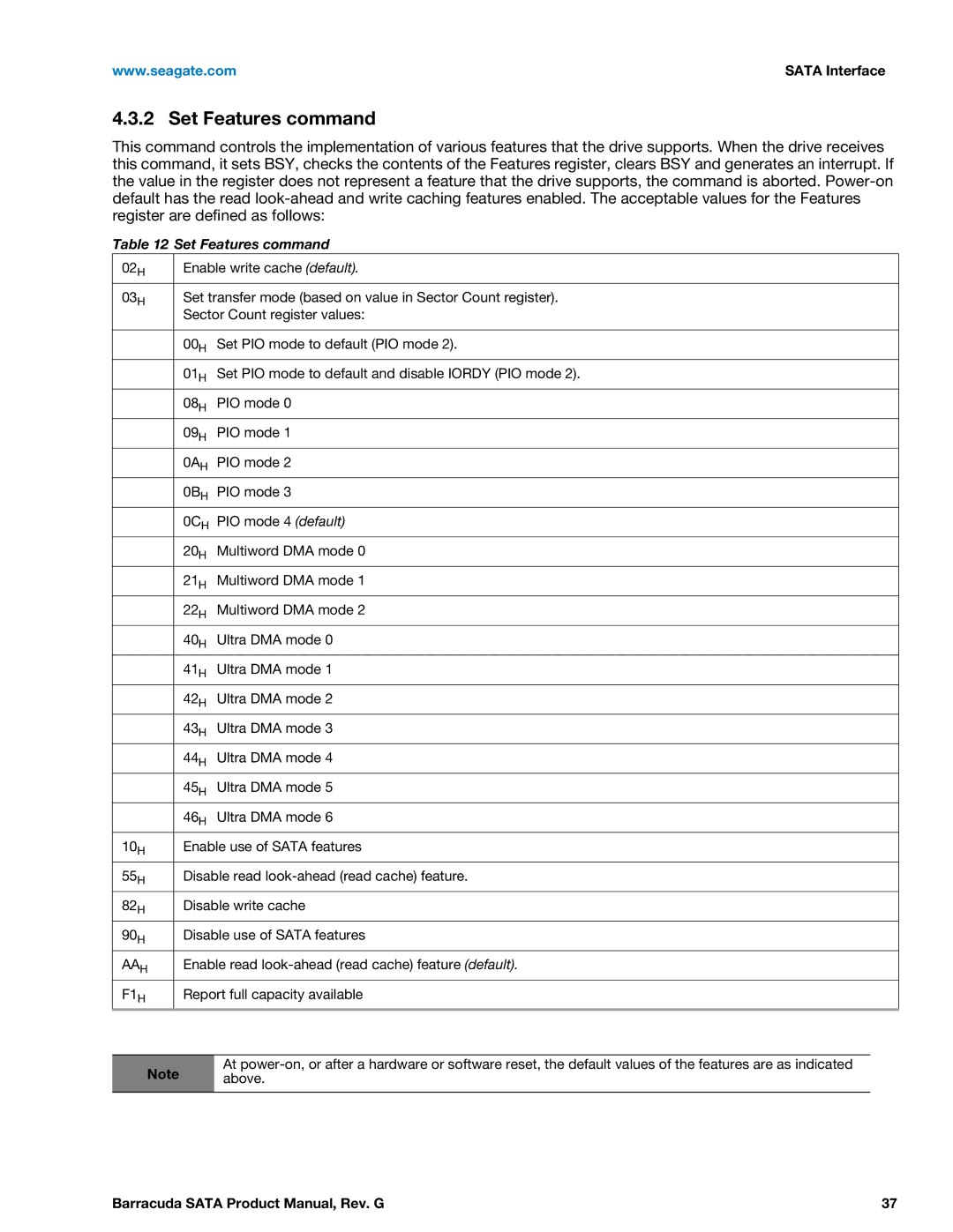
4.3.2 Set Features command

This command controls the implementation of various features that the drive supports. When the drive receives this command, it sets BSY, checks the contents of the Features register, clears BSY and generates an interrupt. If the value in the register does not represent a feature that the drive supports, the command is aborted. Power-on default has the read look-ahead and write caching features enabled. The acceptable values for the Features register are defined as follows:

Table 12 Set Features command

02H

Enable write cache (default).


03H

Set transfer mode (based on value in Sector Count register).


Sector Count register values:


00H

Set PIO mode to default (PIO mode 2).


01H

Set PIO mode to default and disable IORDY (PIO mode 2).


08H

PIO mode 0


09H

PIO mode 1


0AH

PIO mode 2


0BH

PIO mode 3


0CH

PIO mode 4 (default)


20H

Multiword DMA mode 0


21H

Multiword DMA mode 1


22H

Multiword DMA mode 2


40H

Ultra DMA mode 0


41H

Ultra DMA mode 1


42H

Ultra DMA mode 2


43H

Ultra DMA mode 3


44H

Ultra DMA mode 4


45H

Ultra DMA mode 5


46H

Ultra DMA mode 6


10H

Enable use of SATA features


55H

Disable read look-ahead (read cache) feature.


82H

Disable write cache


90H

Disable use of SATA features


AAH

Enable read look-ahead (read cache) feature (default).


F1H

Report full capacity available


At power-on, or after a hardware or software reset, the default values of the features are as indicated

Note above.

Barracuda SATA Product Manual, Rev. G

37

Image 37
Contents Barracuda Revision Date Description of Change Document Revision HistoryContents Barracuda Sata Product Manual, Rev. G Figures Barracuda Sata Product Manual, Rev. G Seagate Technology Support Services Barracuda Sata Product Manual, Rev. G About the Sata interface IntroductionIntroduction Specification summary tables Drive SpecificationsDrive Specifications Drive Specification ST500DM002 ST320DM000 ST250DM000 Formatted capacity Model Formatted Guaranteed Bytes per sector Capacity SectorsDefault logical geometry LBA modeRecording and interface technology Seek time Physical characteristicsPower consumption Power specificationsStart/stop times DiskDC power requirements 3-disk 3TB and 2TB models Power modes Heads Spindle Buffer Power-management modesConducted noise Voltage toleranceTemperature gradient Environmental specifications Ambient temperatureHumidity AltitudeAcoustics Non-operating vibrationAgency certification Safety certification WarrantyTest for Prominent Discrete Tones PDTs Electromagnetic immunityFCC verification Electromagnetic compatibilityKorean RRL Australian C-Tick N176China Restriction of Hazardous Substances RoHS Directive Environmental protectionCorrosive environment Configuring the drive Handling and static-discharge precautionsSata cables and connectors Attaching Sata cabling Drive mountingMounting dimensions 1-disk 1TB and 750GB models Mounting dimensions 1-disk 500GB, 320GB and 250GB models Segment Pin Function Definition Sata InterfaceCommand name Command code in hex Supported ATA commandsE5H EAH E7HECH E3HE6H C6HB0H / DAH E2HWord Description Value Identify Device command0C5AH AsciiBE09H Xx07HFffeh Bit WordMedia serial number is supported 0AH Set Features command0BH 0CHCode in features register A.R.T. command 3 S.M.A.R.T. commandsIndex Barracuda Sata Product Manual, Rev. G Barracuda Sata Product Manual, Rev. G Page Page Americas Seagate Technology LLC