Furuno IB-681 manual Manual call setup sequence

Page 24

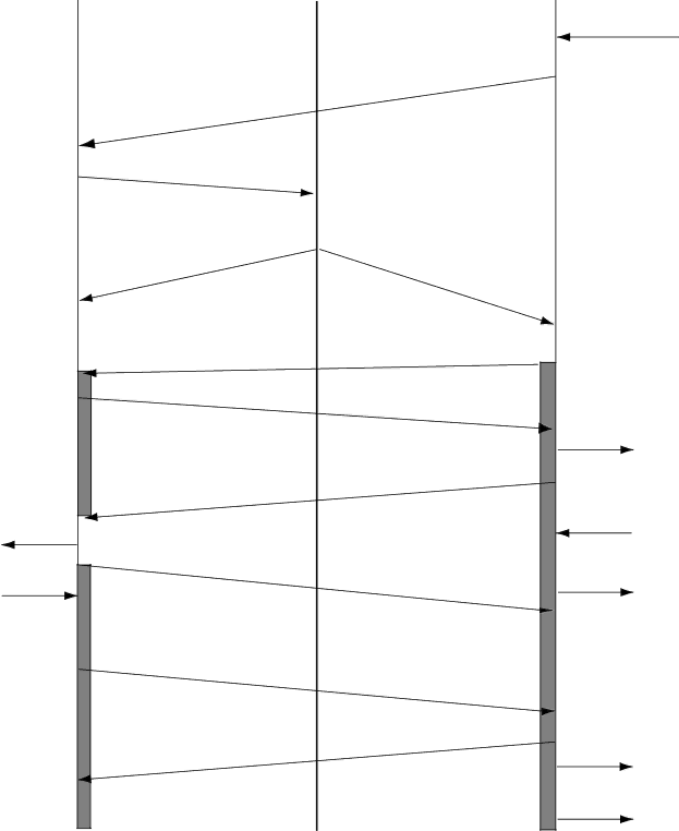
3.4.3 Manual call setup sequence

CES

NCS

FELCOM

Call to

subscriber

Reply from subscriber

SES RQ

CESI

Ch. assignment req. SU

Channal assignment SU

NCSI

HSUB

Scr. vec. ack SU

HSUB

Fill in SU

CES connect

HSUB

Access req. SU

NCSA

Service addr. SU scr. vec. advise SU HSUB

HSUB

HSUB

SES connect SU

Calling operation

(dialing)

RI ON

Ret. carrier ID SU

OFF HOOK

(DTR ON)

RI OFF

DSR ON

CTS/DCD ON

Figure 7 Manual call setup sequence

14

Image 24
Contents Page B . N o . O M E 5 6 0 9 Safety Instructions Safety Information for the OperatorSafety Information for the Installer Electrical Shock HazardTable of Contents Appendix Usage Tips Declaration of conformity to typeFeatures IntroductionInstallation Materials CP16-01601 Installation Materials CP16-01602Equipment List Complete SetInstallation Materials CP16-01603 Installation Materials CP16-01605Optional Equipment System Configuration IB-181IB-281 IB-681Overview Control DescriptionFront panel Rear panel IB-681, rear viewSettings Switch Panel SettingsDIP switches Data rateSW2 Terminal interface OID/DID and IMN Settings Terminal Unit SettingsRegistering, Deleting Subscriber Number Registering subscriber numberDeleting subscriber number Confirming subscriber numberOperation CallingAutomatic HSD call Manual call Tone Name FrequencyInterval Automatic call mode and receiving operation ReceivingSW1 State Remarks V.25bis Command, Indication Receiving and automatic data rate switchingCommand Name Description SW3 State Remarks Command Description Indication DescriptionDirect call setup sequence Call SequenceAddress call setup sequence Address call setup sequenceManual call setup sequence Manual call setup sequenceAutomatic call clear sequence Call clear sequence from landManual call clear sequence Manual call clear sequenceMaintenance & Troubleshooting MaintenanceCleaning Resetting the circuit breakerTroubleshooting for the User ThenGeneral CallingInstallation Mounting procedureMounting Mounting locationWiring Wiring between HSD modem and routerModifying the RF Conv board in the communication unit RS-449 InterfaceAntenna cable Position of R135 Length CPU2 Board 16P0133RF Conv Board RF Conv Board CPU2 BoardR135 J10Mounting of connector assy Rear Panel Board Sub 9 pinWiring between HSD modem and communication unit GroundJ11 Circuit delay Propagation delayRouter setting for network connection Communication with other makes of Inmarsat-B terminalsNetwork configuration Syuchronous -asynchronous adapter Land Earth Station IOR Etilat IB-681 Page Page Page Index