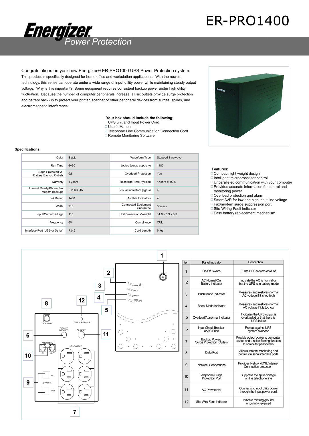
ER-PRO1400
Congratulations on your new Energizer®
This product is specifically designed for home office and workstation applications. With the newest technology, this series can operate under a wide range of input utility power while maintaining steady output voltage. Why is this important? Some equipment requires consistent backup power under high utility fluctuation. Because the number of computer peripherals increase, all six outlets provide surge protection and battery
Your box should include the following:
![]() UPS unit and Input Power Cord
UPS unit and Input Power Cord
![]() User's Manual
User's Manual
![]() Telephone Line Communication Connection Cord
Telephone Line Communication Connection Cord
![]() Remote Monitoring Software
Remote Monitoring Software
Specifications
Color | Black | Waveform Type | Stepped Sinewave | |
|
|
|
| |
Run Time | 6~60 | Joules (surge capacity) | 1482 | |
|
|
|
| |
Surge Protected vs. | 0:6 | Overload Protection | Yes | |
Battery Backup Outlets | ||||
|
|
| ||
|
|
|
| |
Warranty | 3 years | Recharge Time (typical) | <=8hrs of 90% | |
|
|
|
| |
Internet Ready/Phone/Fax | RJ11/RJ45 | Visual Indicators (lights) | 4 | |
Modem hookups | ||||
|
|
| ||
|
|
|
| |
VA Rating | 1400 | Audible Indicators | 4 | |
|
|
|
| |
Watts | 910 | Connected Equipment | 3 Years | |
Guarantee | ||||
|
|
| ||
|
|
|
| |
Input/Output Voltage | 115 | Unit Dimensions/Weight | 14.6 x 5.9 x 8.3 | |
|
|
|
| |
Frequency | 60 | Compliance | CUL | |
|
|
|
| |
Interface Port (USB or Serial) | RJ48 | Cord Length | 6 feet | |
|
|
|
|
Features:
![]() Compact light weight design
Compact light weight design
![]() Intelligent microprocessor control
Intelligent microprocessor control
![]() Unparalleled communication with your computer
Unparalleled communication with your computer
![]() Provides accurate information for control and monitoring power
Provides accurate information for control and monitoring power
![]() Overload protection and alarm
Overload protection and alarm
![]() Smart AVR for low and high input line voltage
Smart AVR for low and high input line voltage
![]() Fax/modem surge suppression port
Fax/modem surge suppression port
![]()
![]() Easy battery replacement mechanism
Easy battery replacement mechanism
6
10
9
|
| 12 | |
8 |
| ||
|
|
| |
|
|
|
|
|
|
|
|
|
|
|
|
DATA PORT | SITE WIRE FAULT | |
| ||
| CIRCUIT | AC INPUT |
| BREAKER | |
FAX/MODEM |
| |
|
| UPS OUTPUT |
IN | OUT |
|
IN
NETWORK
OUT
1
2
3 | AC |
| BATT |
4 | BUCK |
BOOST | |
| OVERLOAD |
5
11
Item | Panel Indicator | Description | |
1 | On/Off Switch | Turns UPS system on & off | |
|
|
| |
2 | AC Normal/On | Indicate the AC is normal or | |
Battery Indicator | that the UPS is in battery mode | ||
| |||
3 | Buck Mode Indicator | Measures and restores normal | |
AC voltage if it is too high | |||
4 | Boost Mode Indicator | Measures and restores normal | |
AC voltage if it is too low | |||
|
| ||
5 |
| Indicates the UPS output is | |
Overload/Abnormal Indicator | overloaded or that there is | ||
|
| UPS failure | |
6 | Input Circuit Breaker | Protect against UPS | |
or AC Fuse | system overload | ||
| |||
|
|
| |
| Backup Power/ | Provide output power to computer | |
7 | device and a noise filtering function | ||
Surge Protection Outlets | |||
|
| to computer peripherals | |
8 | Data Port | Allows remote monitoring and | |
control via serial interface ports | |||
|
| ||
|
|
| |
9 | Network Connections | Provides Network/DSL/Internet | |
Connection protection | |||
|
| ||
|
|
| |
10 | Telephone Surge | Suppress the spike voltage | |
Protection Port | on the telephone line | ||
| |||
|
|
| |
11 | AC Power/Inlet | Connects to input utility power | |
through the input power cord. | |||
|
| ||
|
|
| |
12 | Site Wire Fault Indicator | Indicate missing ground | |
or polarity reversed | |||
|
| ||
|
|
|
7

