Dell C610, C510 manual Removing the 14.1-Inch Display Bezel, Inch Display Bezel and Panel

Page 22

Display Assembly, Display Latch, and Hinge Covers: Dell Latitude C610/C510 Service Manual

1 M2 x 3-mm screws (2)

9.Pull up on the pull tab that is attached to the display-feed flex cable connector to remove it from the interface connector on the system board.

10.Lift the display assembly up and out of the bottom case.

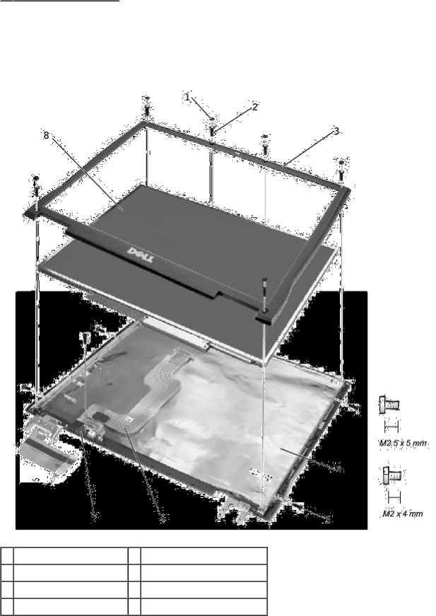
14.1-Inch Display Bezel and Panel

1

rubber screw covers (6)

5

M2 x 4-mm screws (5)

2

M2.5 x 5-mm screws (6)

6

display-feed flex cable

3

display bezel

7

flex-cable retention bracket

4

top cover

8

display panel

Removing the 14.1-Inch Display Bezel

NOTICE: Disconnect the computer and any attached devices from electrical outlets, and remove any installed

file:///C/Work%20Area%20-%20A/E%20DOC%20Posting/latc610/service%20manual/display.htm[2/1/2013 11:00:46 AM]

Image 22
Contents January 2002 Rev. A01 Preparing to Work Inside the Computer Before You BeginRecommended Tools Screw Identification Screw IdentificationComputer Orientation Back Right Front 4 leftDisplay Bezel Hard Drive Door Keyboard to EachBottom Case Each 1 each Each 3 each Back to Contents Exploded View Display assembly Bottom case Center control coverSystem Components KeyboardFan guard Hard Drive Removal Hard DriveRemoving the Hard Drive Bottom of computer M3 x 5-mm screw 3 hard drive doorReplacing the Hard Drive Removing the Memory Module Cover Memory Modules, Mini PCI Card, and ModemMemory Modules Memory Module CoverReplacing the Memory Modules Removing the Memory ModulesMemory Module Removal Removing the Mini PCI Card Mini PCI CardMini PCI Card Replacing the Mini PCI Card Antenna connectors on card 2 2 antenna cablesModem Removing the ModemReplacing the Modem M2 x 3-mm screws Modem connector Modem cable 4 pull tabModem Removal Page Removing the Keyboard KeyboardScrew Removal Center Control Cover Removal Keyboard RemovalKeyboard Connector Removal Replacing the Keyboard Back to Contents Display Assembly Display Assembly, Display Latch, and Hinge CoversDisplay Assembly Display-Feed Flex Cable Connector Remove the center control coverInch Display Bezel and Panel Removing the 14.1-Inch Display BezelTop cover Display panel Display-Feed Flex Cable Connections Removing the 14.1-Inch Display PanelBatteries Remove the hard drive Replacing the 14.1-Inch Display Panel Replacing the Display Latch Display LatchRemoving the Display Latch Display Latch Removal 14.1-Inch XGA Panel ShownRemoving the Hinge Covers Hinge Cover ReplacementHinge Covers Replacing the Hinge CoversRight hinge cover 2 left hinge cover Palm Rest Screw Removal Palm RestRemoving the Palm Rest Remove the hard drive Remove the keyboardPalm Rest Removal Back to Contents Microprocessor Thermal Cooling Assembly Removal Microprocessor Thermal Cooling AssemblyRemoving the Microprocessor Thermal Cooling Assembly Microprocessor thermal cooling assembly 2 captive screwsReplacing the Microprocessor Thermal Cooling Assembly Removing the Microprocessor Module Microprocessor ModuleMicroprocessor Module Removal Remove the microprocessor thermal cooling assembly Replacing the Microprocessor ModuleHybrid Cooling Fan Removal Hybrid Cooling FanRemoving the Hybrid Cooling Fan Remove the palm restM2 x 3-mm screw Reserve Battery Removal Reserve BatteryRemoving the Reserve Battery Reserve battery Speaker connectorReplacing the Reserve Battery System board connector 4 reserve battery cableFlashing the Bios Flashing the BiosRemoving the Speaker Assemblies Speaker AssembliesRouting the Left Speaker Cable Speaker Orientation Speaker Assemblies Antenna cable In-line connector Replacing the Speaker Assemblies Removing the System Board System BoardSystem Board Screw Removal System Board Removal M2.5 x -mm screwReplacing the System Board Removing the Battery and Module Bay Latches Battery and Module Bay LatchesBattery and Module Bay Latches Replacing the Battery and Module Bay Latches Serial Connector Pin Assignments for I/O ConnectorsUSB Connector DataVideo Connector Parallel Connector18-23 PS/2 Connector Video TV-Out ConnectorDocking Connector 123 121122 124163 161162 164Back to Contents
Related manuals
Manual 138 pages 13.75 Kb