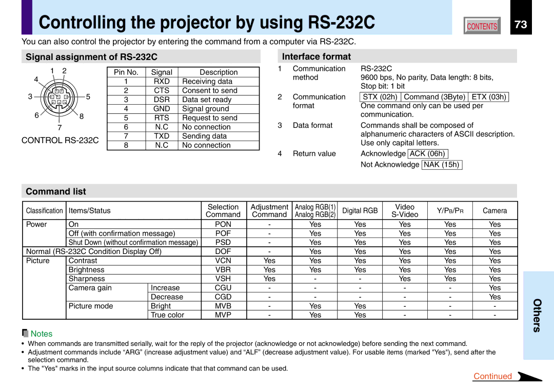
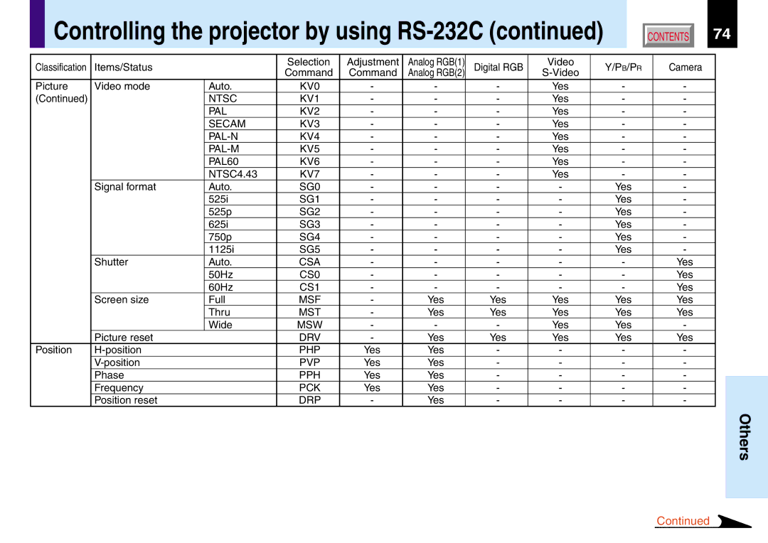
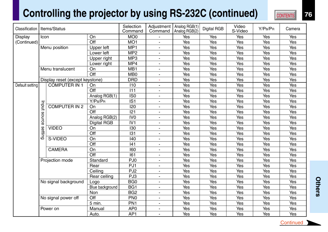
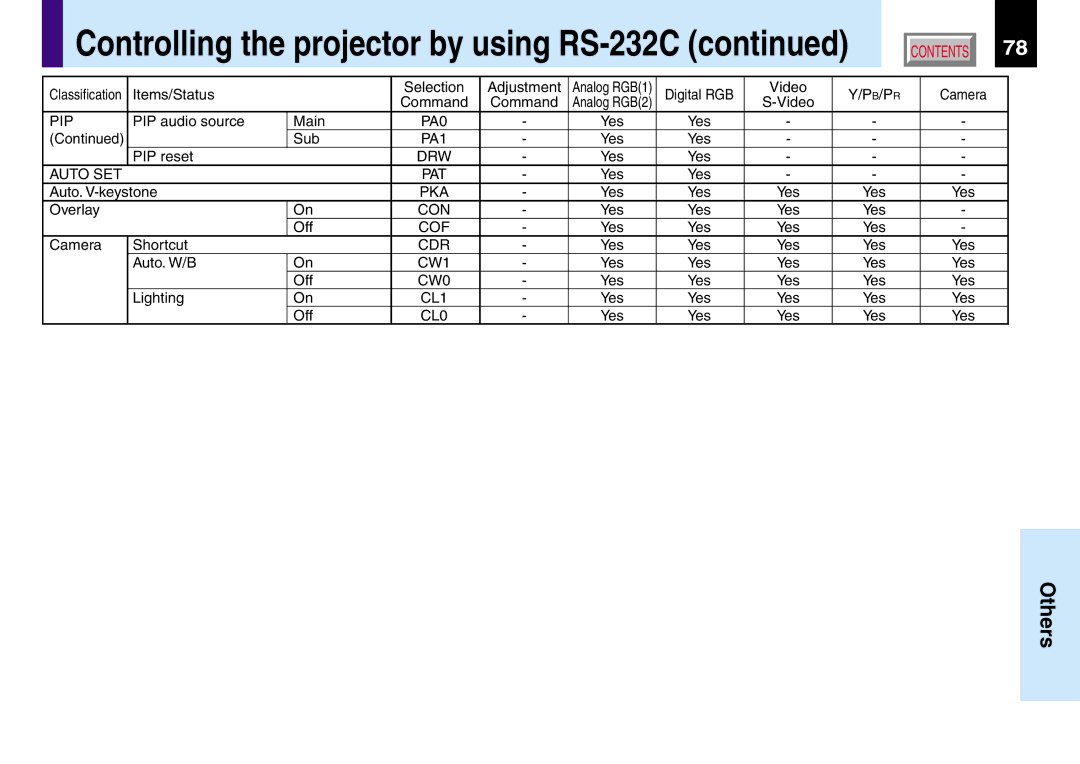
Toshiba TLP780U TLP781U owner manual Mini D-sub 15pin Connector, Do not connect anything

Page 70

Pin assignment of COMPUTER IN, MONITOR OUT connector

CONTENTS

70

COMPUTER IN 1


COMPUTER IN 2


MONITOR OUT

Input signal


Analog input signal


C5 16


Analog R, G, B signal: 0.7V(p-p) 75

11

15

Analog R, G, B signal: 0.7V(p-p) 75


Horizontal sync signal:

C4 C3 24

17

9

Horizontal sync signal:

6

10


TTL level (positive/negative polarity)


TTL level (positive/negative polarity)


Vertical sync signal:


Vertical sync signal:


TTL level (positive/negative polarity)


TTL level (positive/negative polarity)

1

5

Y signal: 1.0V(p-p) 75

C2 C1 8

1


PB, PR signal: 0.7V(p-p) 75


DVI ANALOG & DIGITAL


Mini D-sub 15pin


connector


connector


Pin No.

Description


RGB input


Y/PB/PR input


1

Video signal (Red)


Color difference signal (PR)

2

Video signal (Green)


Luminance signal (Y)

3

Video signal (Blue)


Color difference signal (PB)

4

GND


*

5

GND


*

6

GND (Red)


GND (PR)

7

GND (Green)


GND (Y)

8

GND (Blue)


GND (PB)

9

N.C


*

10

GND


*

11

GND


*

12

DDC data


*

13

Horizontal sync signal


*

14

Vertical sync signal


*

15

DDC clock


*

*: Do not connect anything.

Pin No.

Description

1

T.M.D.S. data 2 -

2

T.M.D.S. data 2 +

3

T.M.D.S. data 2/4 shield

4

T.M.D.S. data 4 -

5

T.M.D.S. data 4 +

6

DDC clock

7

DDC data

8

Analog vertical sync signal

9

T.M.D.S. data 1 -

10

T.M.D.S. data 1 +

11

T.M.D.S. data 1/3 shield

12

T.M.D.S. data 3 -

13

T.M.D.S. data 3 +

14

+5V power

15

GND (+5V, H Sync & V Sync)

Pin No.

Description

16

Hot plug detection

17

T.M.D.S. data 0 -

18

T.M.D.S. data 0 +

19

T.M.D.S. data 0/5 shield

20

T.M.D.S. data 5 -

21

T.M.D.S. data 5 +

22

T.M.D.S. clock shield

23

T.M.D.S. clock +

24

T.M.D.S. clock -

C1

Analog Video signal (Red)

C2

Analog Video signal (Green)

C3

Analog Video signal (Blue)

C4

Analog horizontal sync signal

C5

Analog GND (R,G & B)

Others

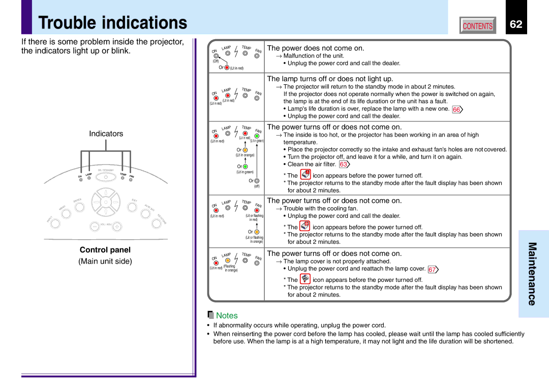
Image 70
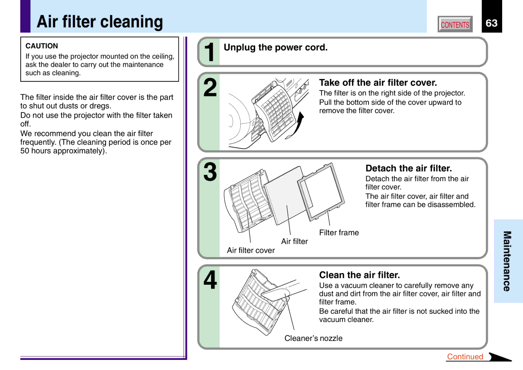
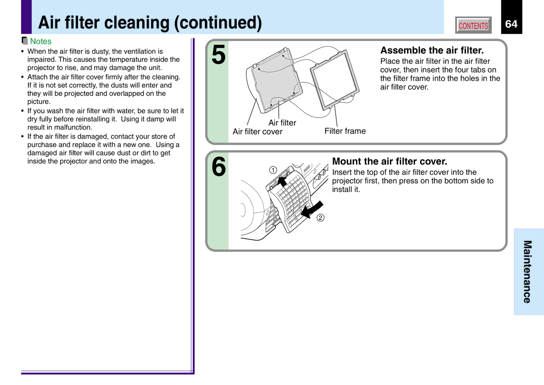
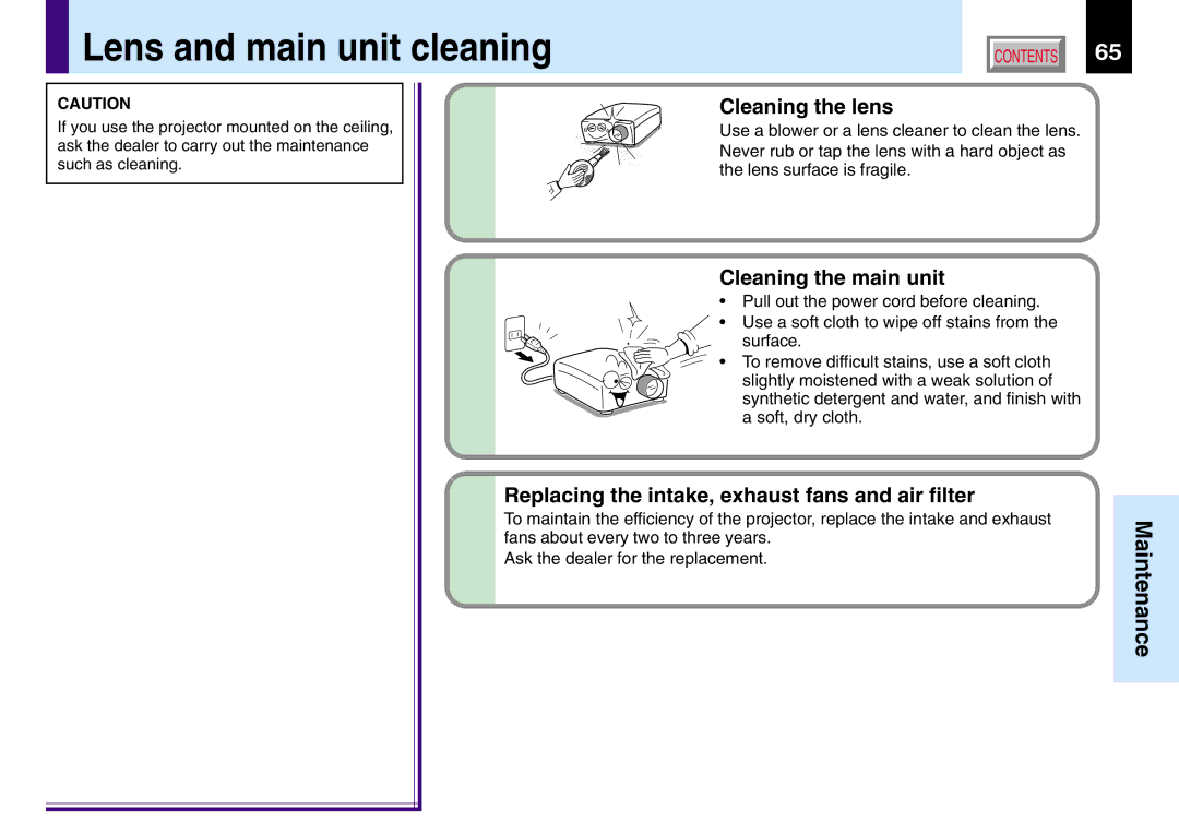
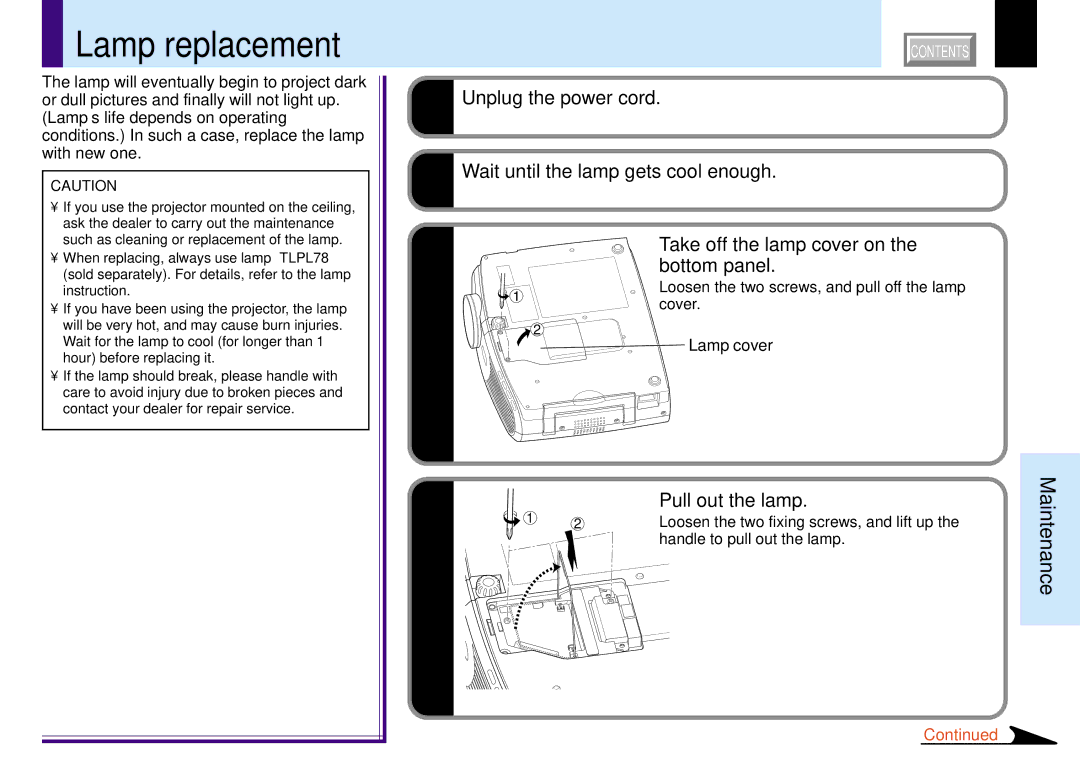
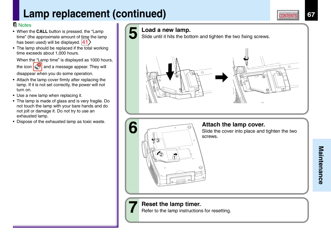
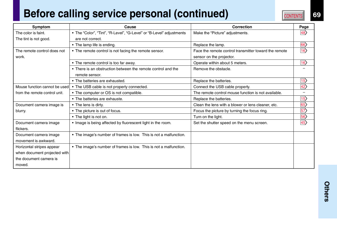
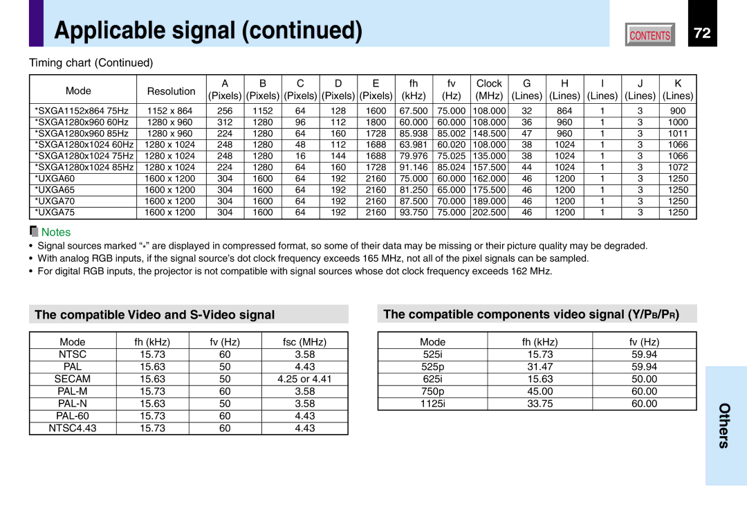
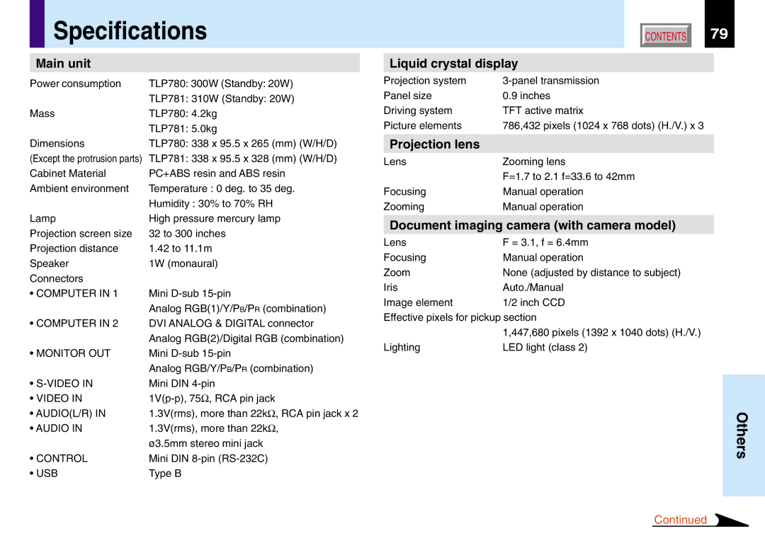
Contents TLP780U Safety Precautions Important Precautions Important Safety Instructions Important Safety Instructions HeatObject and Liquid Entry Damage Requiring Service Do not carry by the camera arm Strong light may cause damage to your eyes or sightPower supply cord selection Contents Explanation here is only for the model without the document Names of each part on the main unitRefer to Top side Names of each part on the main unitMenu button Input button Right side Names of each part on the remote control Open the cover Install the batteriesLoading batteries Attach the coverFront side Remote control operationRear side Floor-mounted projector placement ViewerTop view Determine the screen size projected on the screenSide view Take off the lens cover Connect the power cordLight Orange Power cord Supplied Insert the other end into a wall outletLift up Lower Projector placement angle adjustmentFoot adjuster Foot adjuster release button Turn clockwise to lift up Turn counterclockwise to lowerCeiling-mounted projector placement Viewer Translucent screenConnecting a computer Computer in 1 connector Connecting a computer Computer in 2 connector Connecting video equipment Connectionsand Projector operation control by a computer ComputerHow to use the output connector Press ON/STANDBY Projection on the screenLamp lights and the start up display appears Language Turn on the connected equipment and put it in playback modePress Enter to confirm Dialog box to find and designate this filePress Enter Select the input source by pressing Input repeatedlyPress Input and hold for two seconds Input source selection menu appearsStill picture is recommended for focusing Adjust the picture size by turningFocusing ring Zooming leverPress VOL/ADJ +/- to adjust volume About the LCD PanelPress ON/STANDBY after using the projector Turning the power offPress ON/STANDBY again Source computer and project the image Adjusting the picture automaticallyInput full screen video signals from the input Press Auto SETPress Keystone Correcting the keystone distortionConfirm the keystone distortion Keystone adjustment finishes After confirming that V-keystone is selected on the menuPress Mute Icon appears in the mute modeCutting off the picture and sound temporarily Sound and picture are cut off temporarilyPress Freeze Icon appears in the freeze modeFreezing the picture Picture freezesEnlarging the picture size Icon appears in the resize modePress Resize Press PIP Displaying PIP Sub-picturesSub-picture is displayed Displaying Information Press CallOperating a computer by the remote control Press Menu once again Operating the menu screenPress Menu Select the item with the selection ButtonsEnter Press Enter Adjust with VOL/ADJ +Select the item with selection buttons Press EnterGuide Menu adjustments and settings ShutterFull Menu adjustments and settings Picture Full Menu adjustments Position Full Menu adjustments Color Full Menu adjustments and settings Audio Full Menu adjustments and settings Display Settings AdjustmentsFull Menu settings Default setting Full Menu settings Reset Reset allPIP menu setting ImagingDocument camera Preparation of the document imaging camera Set a document to be projected Press ARM LightCamera head over them Press Camera to select the camera input mode Move the camera head to adjust the size of the pictureCamera subject which is too dark or vivid When finished, turn off the light and close itPress Camera Gain +/- to improve view of a Put back the armOverlaying projection Project a white paper and enlarge it to fill Balance Press W.BALANCE to turn the Lock indicatorLocking the white balance ScreenCover the camera lens with a piece of black Correcting illuminated defectsWith the document camera operating, fully Paper or clothTrouble indications Main unit sideClean the air filter Air filter cleaningUnplug the power cord Take off the air filter cover Detach the air filterMount the air filter cover Assemble the air filterAir filter Air filter cover Cleaning the main unit Lens and main unit cleaningCleaning the lens Replacing the intake, exhaust fans and air filterTake off the lamp cover on the bottom panel Lamp replacementUnplug the power cord Wait until the lamp gets cool enough Pull out the lamp Attach the lamp cover Reset the lamp timer Load a new lamp Slide the cover into place and tighten the two screwsBefore calling service personal Symptom Cause CorrectionBefore calling service personal Mini D-sub 15pin Connector Do not connect anythingSignal Timing Horizontal Signal Timing Vertical Applicable signalApplicable computer signal Timing chartCompatible Video and S-Video signal Applicable signalCompatible components video signal Y/PB/PR Signal assignment of RS-232C Interface format Controlling the projector by using RS-232CCommand list Controlling the projector by using RS-232C VCL MO0 MS0 PIP Liquid crystal display SpecificationsMain unit Projection lensReplacement lamp SpecificationsAccessories Sold separatelyStep-by-step procedure how to obtain warranty service Limited two 2 Years Warranty of Parts and LaborYour Responsibility Limited Warranty