4 - 6 | I n s t a l l a t i o n |
3Carefully dress the excess fiber into the ramp of the fiber spool tray. Wrap the fiber around the spooling cylinder one to two times depending on the length of the fiber. The diameter of the spool tray is matched to the bend radius of the fiber. Also ensure that the fiber is routed under the retaining flanges and through the pegs of the fiber tray for proper routing to the optics modules. Figures
Figure
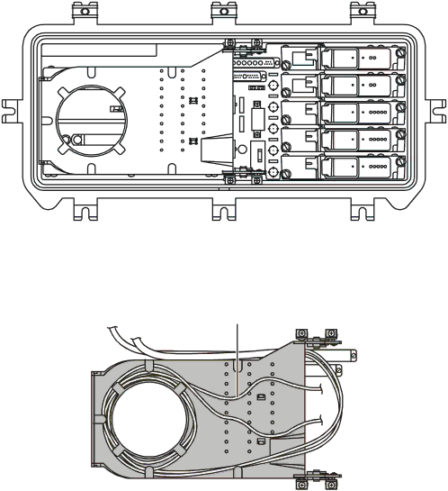
Housing lid and fiber spool tray
Figure
Fiber spool tray
Fiber routed to optics modules
through fiber tray pegs
SG 2000 Installation and O peration Manual