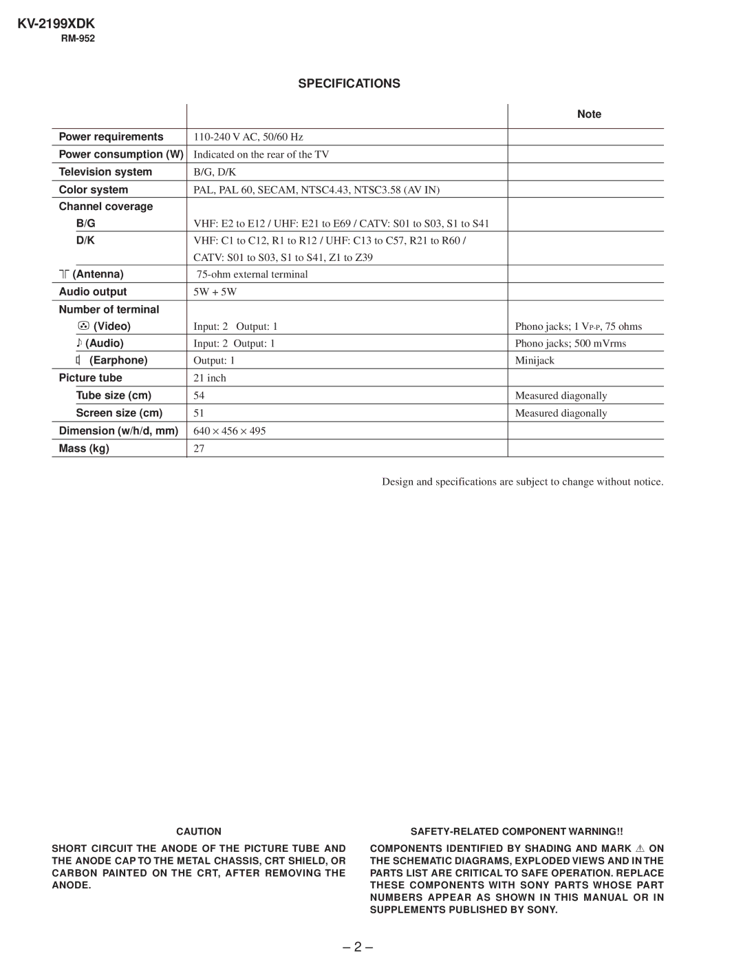
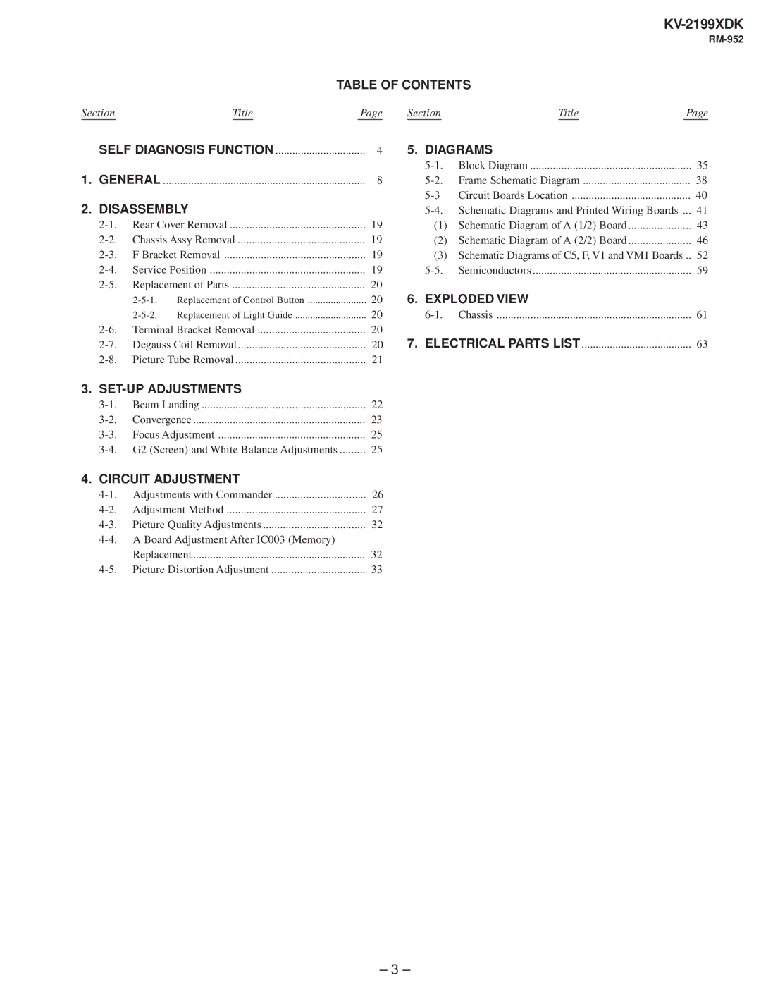
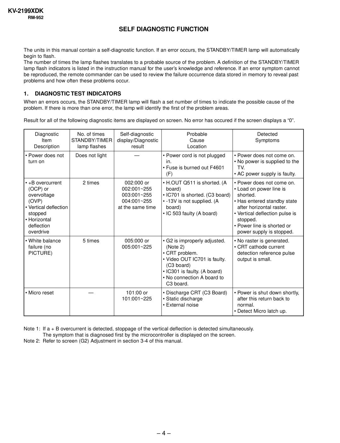
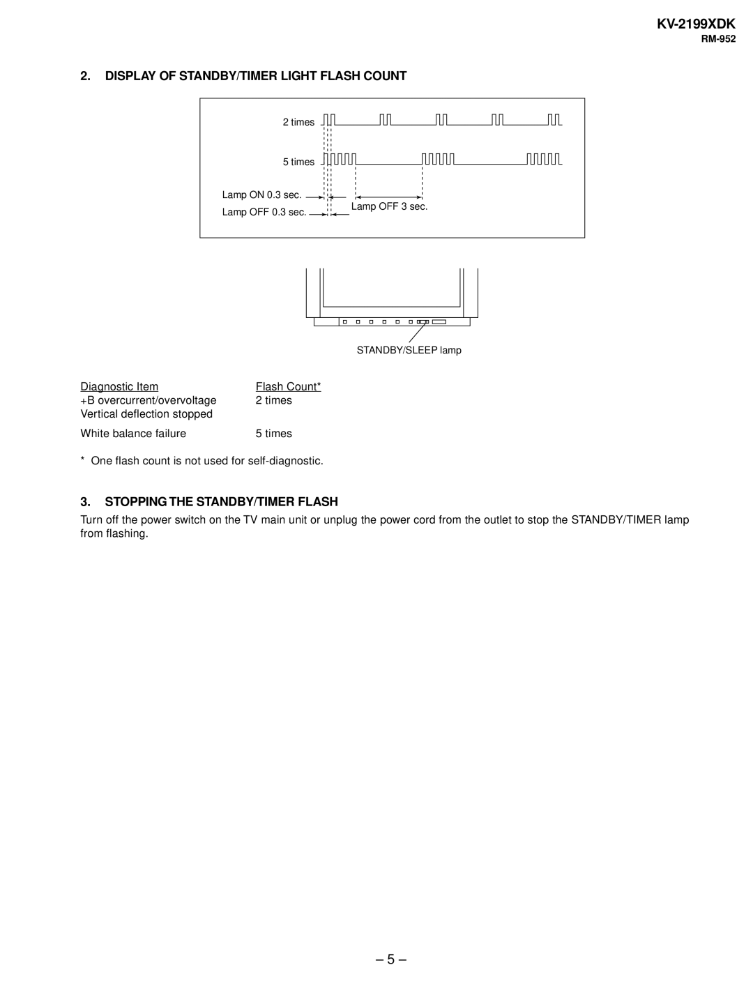
Canon KV-2199XDK Table of Contents, Diagrams, Disassembly, Exploded View, SET-UP Adjustments

Page 3

KV-2199XDK

RM-952

TABLE OF CONTENTS

SectionTitlePage SectionTitlePage

SELF DIAGNOSIS FUNCTION

4

5. DIAGRAMS


5-1.

Block Diagram

35

1. GENERAL

8

5-2.

Frame Schematic Diagram

38


5-3

Circuit Boards Location

40

2. DISASSEMBLY


5-4. Schematic Diagrams and Printed Wiring Boards ...

41

2-1.

Rear Cover Removal

19

(1) Schematic Diagram of A (1/2) Board

43

2-2.

Chassis Assy Removal

19

(2) Schematic Diagram of A (2/2) Board

46

2-3.

F Bracket Removal

19

(3) Schematic Diagrams of C5, F, V1 and VM1 Boards ..

52

2-4.

Service Position

19

5-5.

Semiconductors

59

2-5.

Replacement of Parts

20


2-5-1. Replacement of Control Button

20

6. EXPLODED VIEW


2-5-2. Replacement of Light Guide

20

6-1.

Chassis

61

2-6.

Terminal Bracket Removal

20


2-7.

Degauss Coil Removal

20

7. ELECTRICAL PARTS LIST

63

2-8.

Picture Tube Removal

21


3. SET-UP ADJUSTMENTS


3-1.

Beam Landing

22


3-2.

Convergence

23


3-3.

Focus Adjustment

25


3-4. G2 (Screen) and White Balance Adjustments

25


4. CIRCUIT ADJUSTMENT


4-1.

Adjustments with Commander

26


4-2.

Adjustment Method

27


4-3.

Picture Quality Adjustments

32


4-4. A Board Adjustment After IC003 (Memory)


Replacement

32


4-5.

Picture Distortion Adjustment

33


– 3 –

Image 3
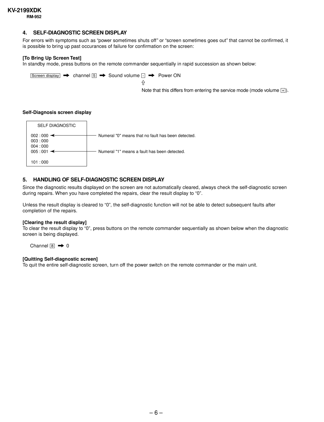
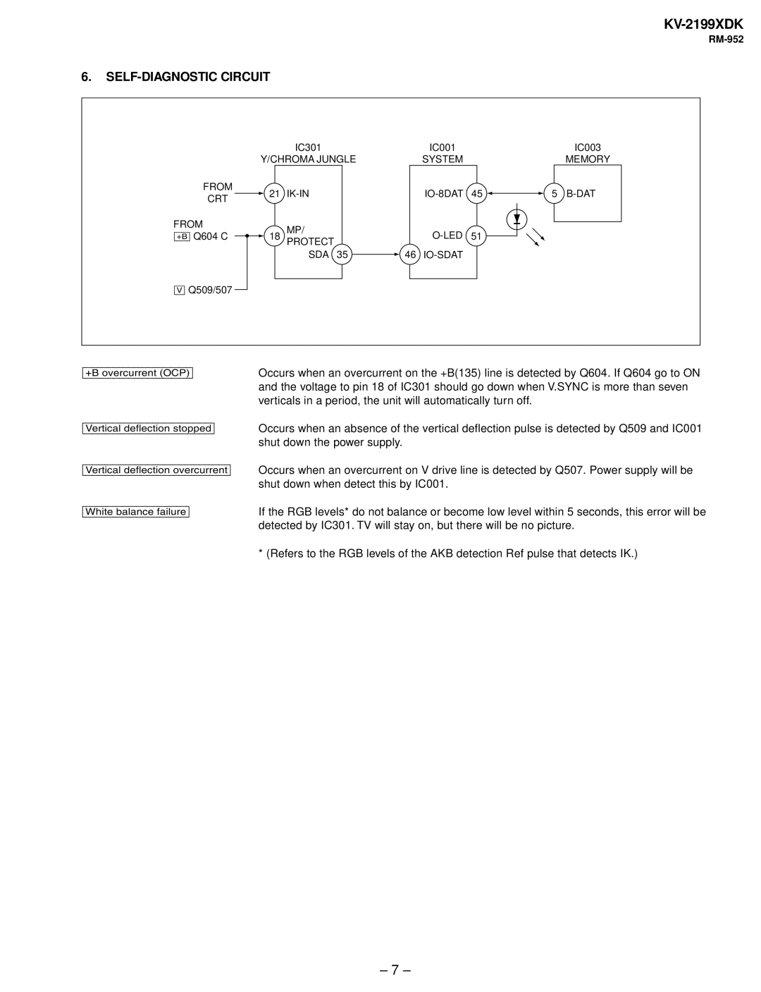
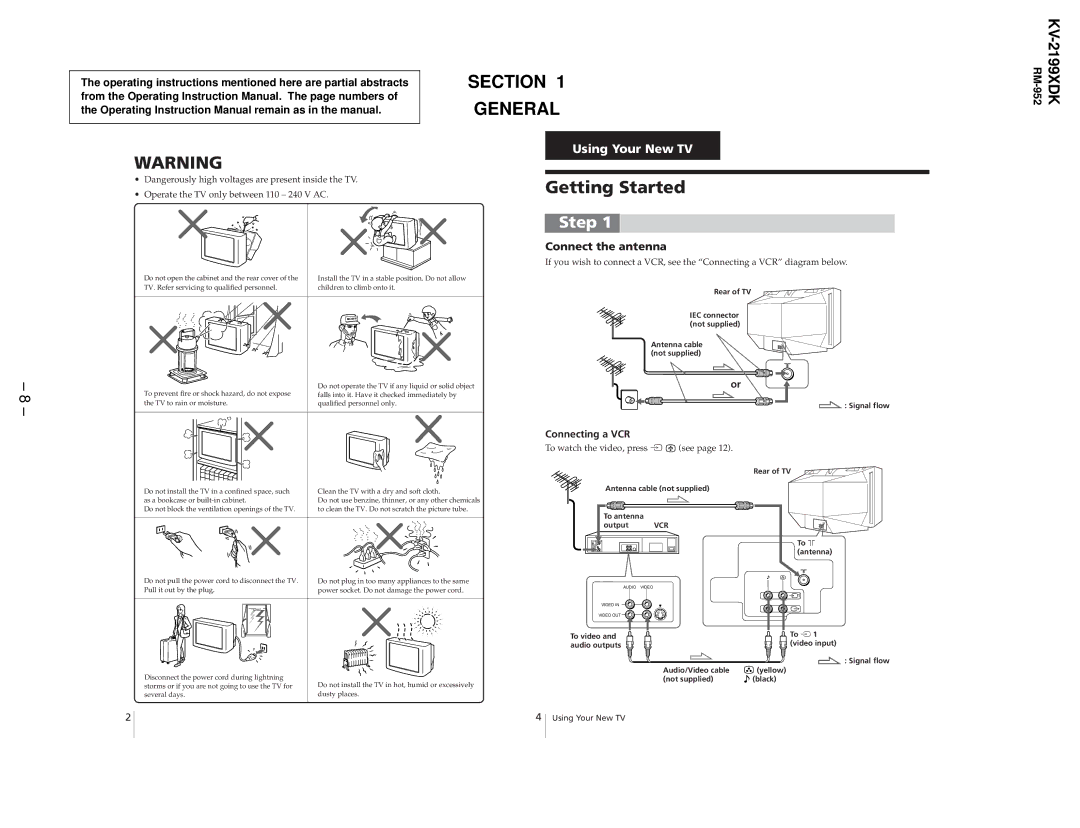
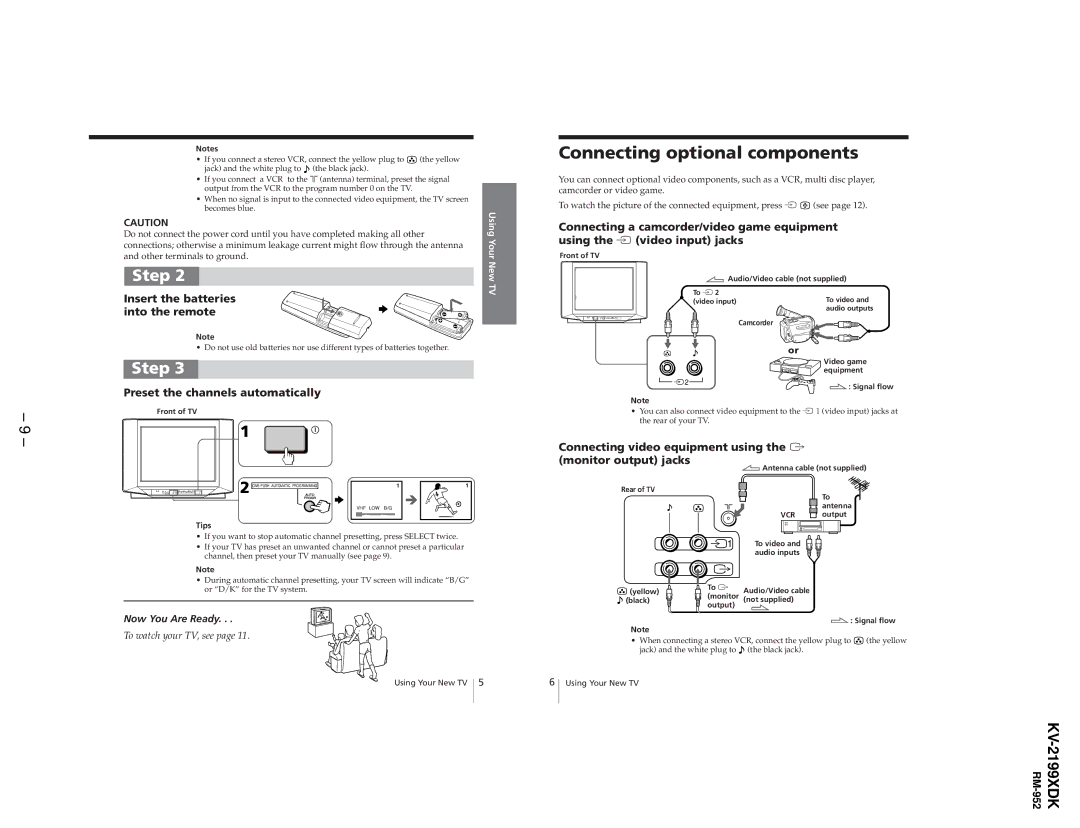
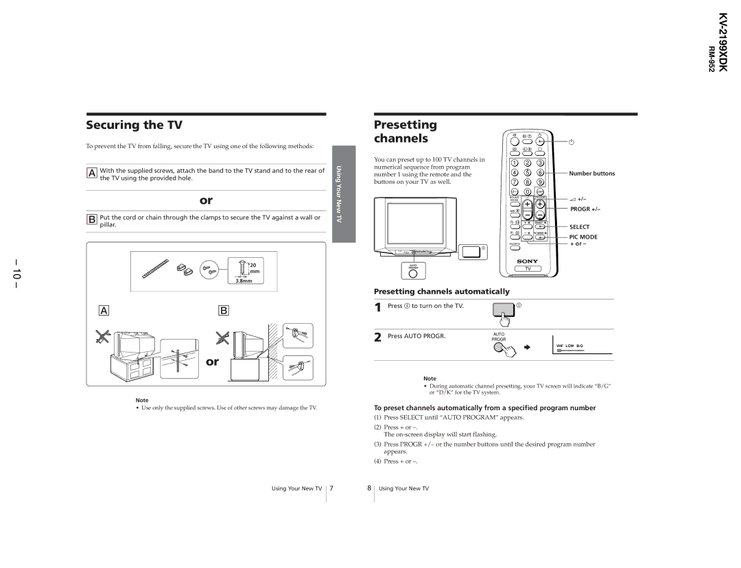
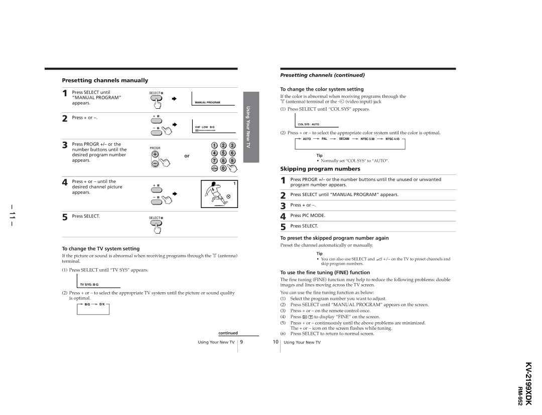
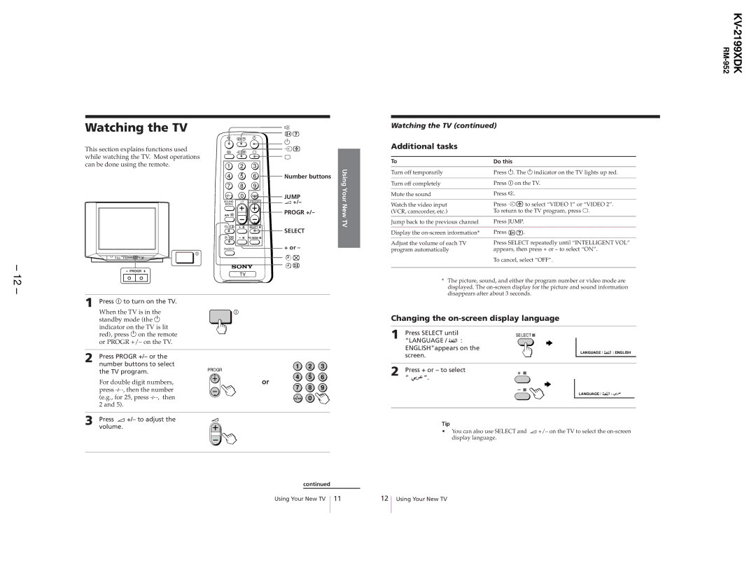
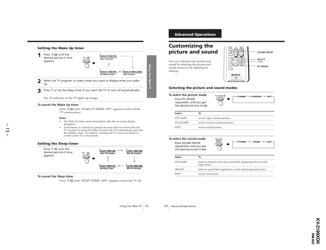
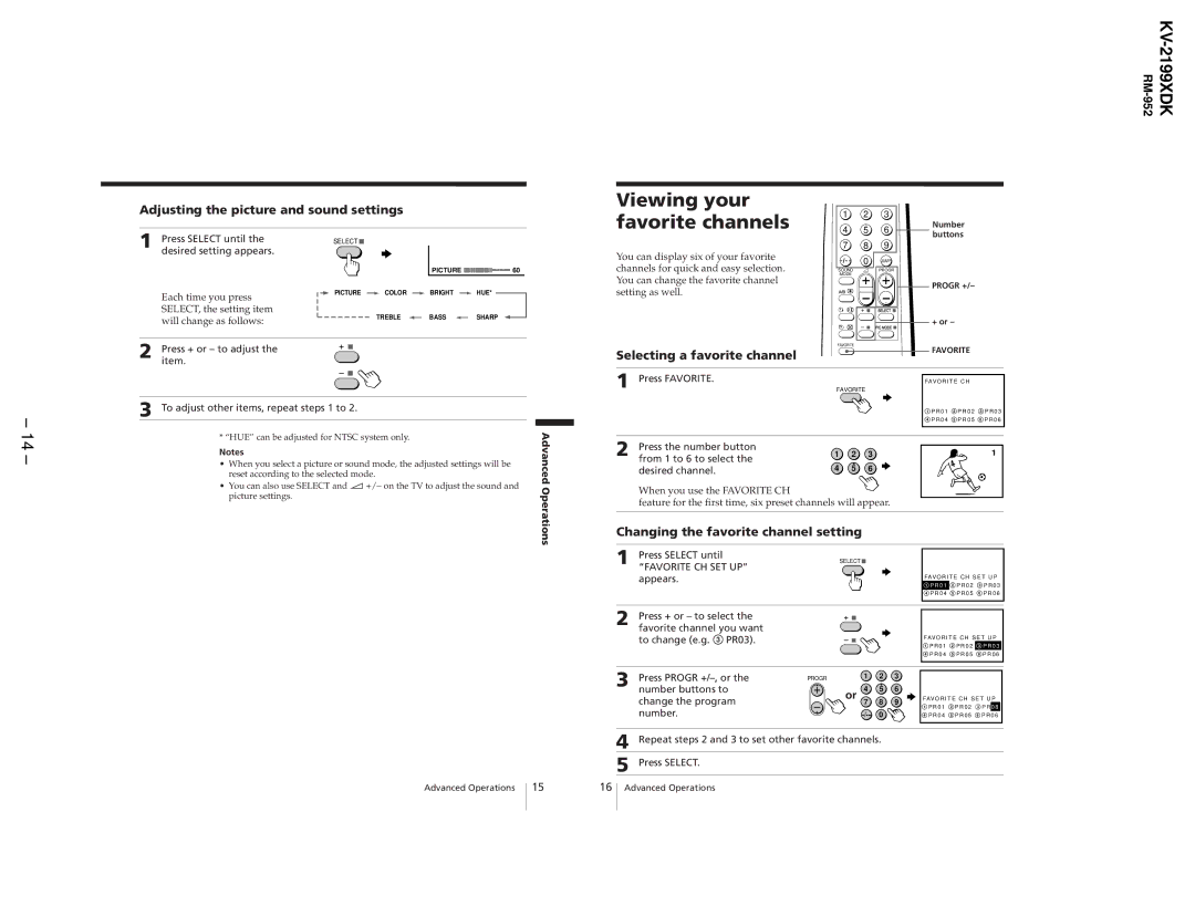
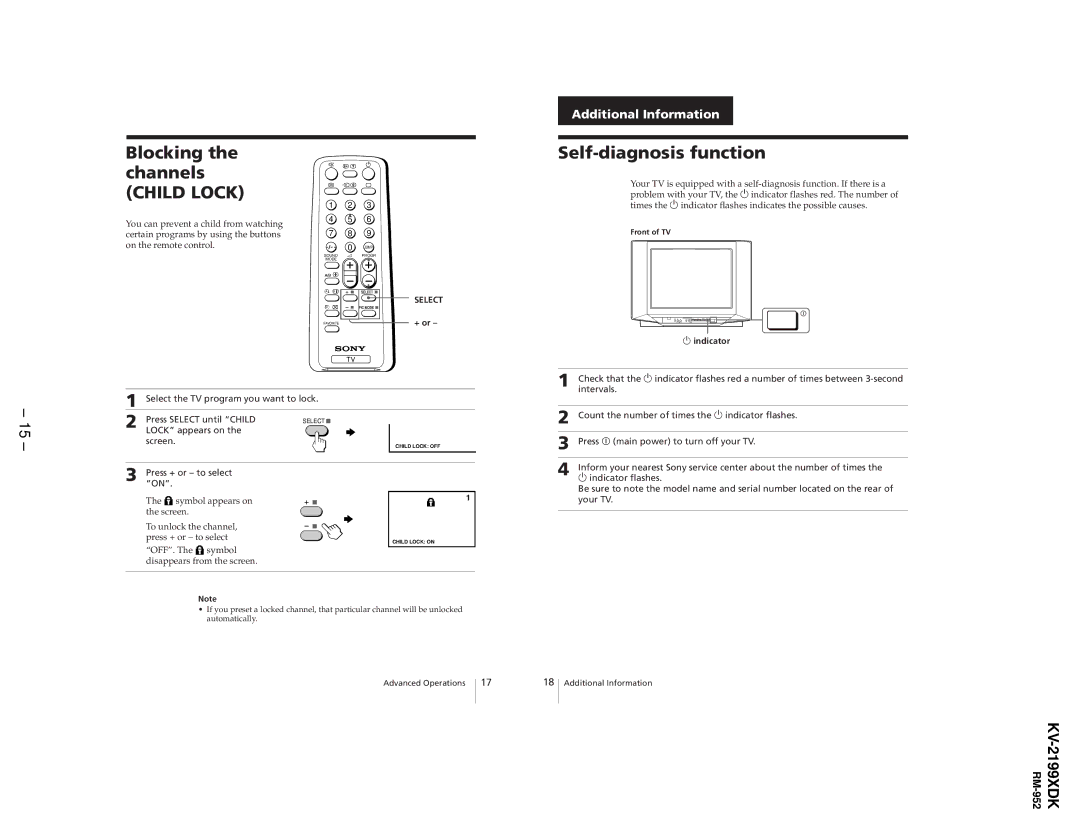
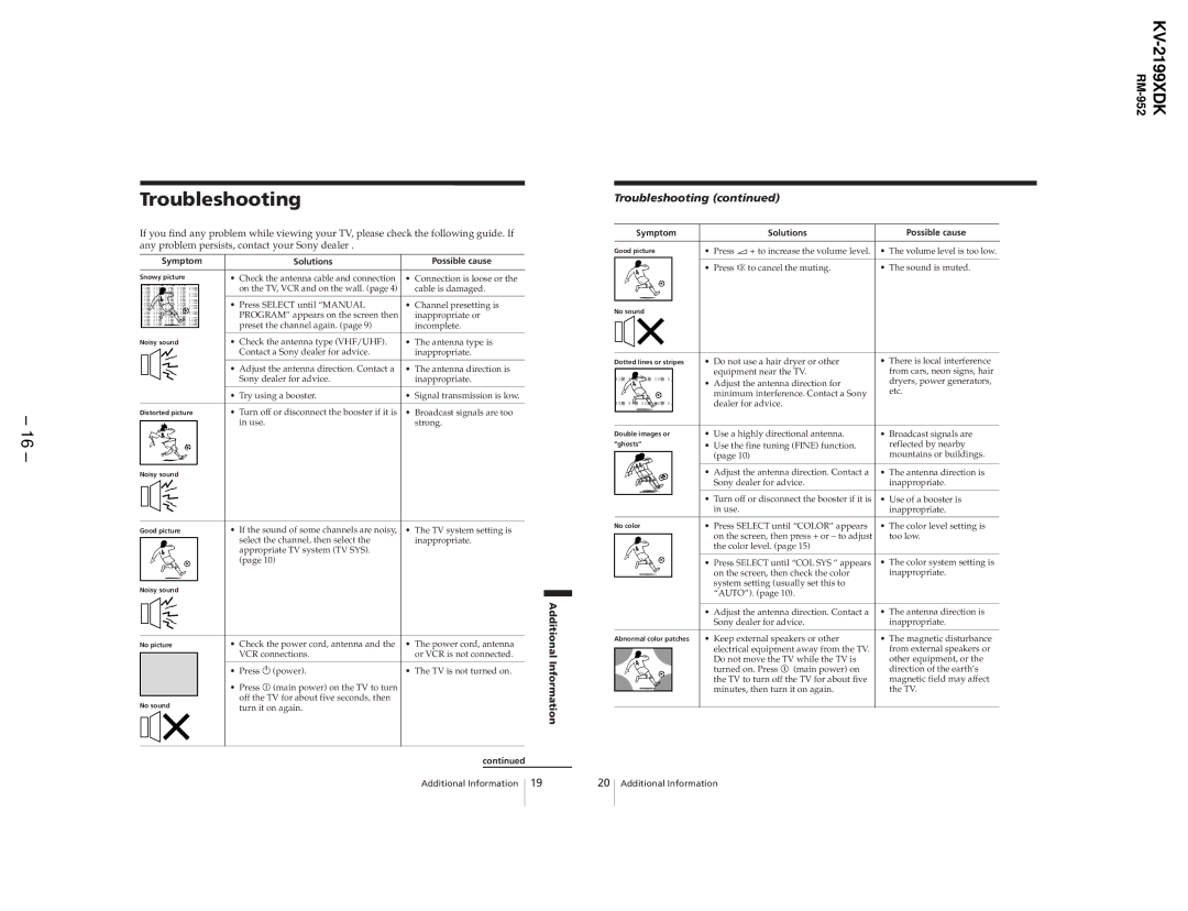
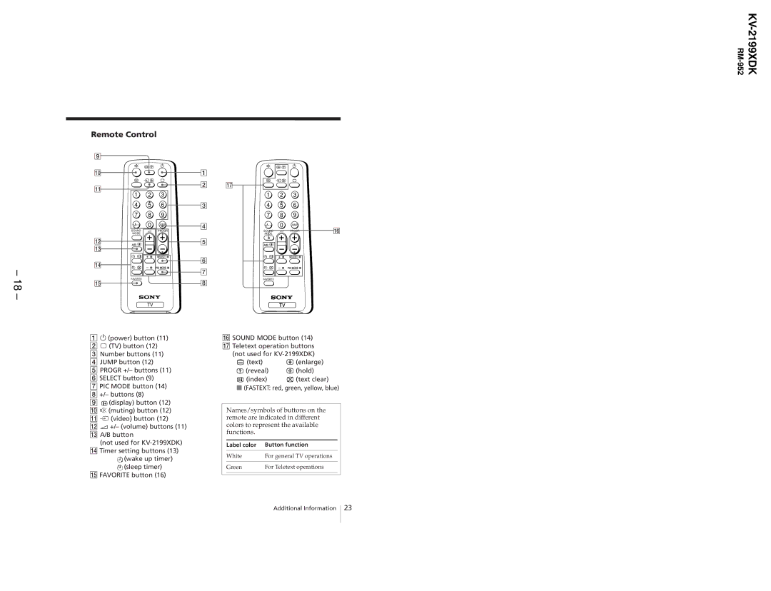
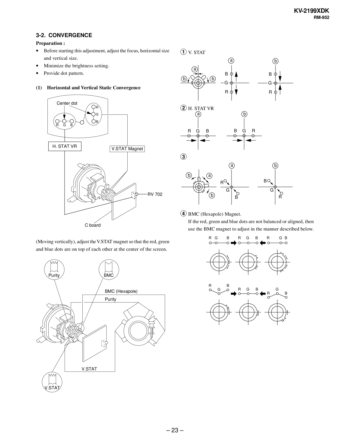
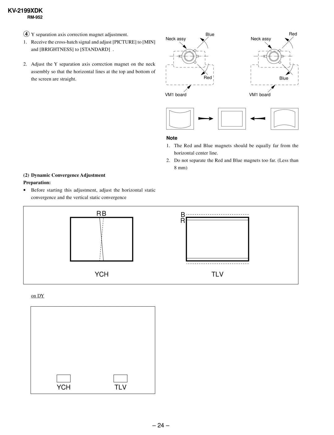
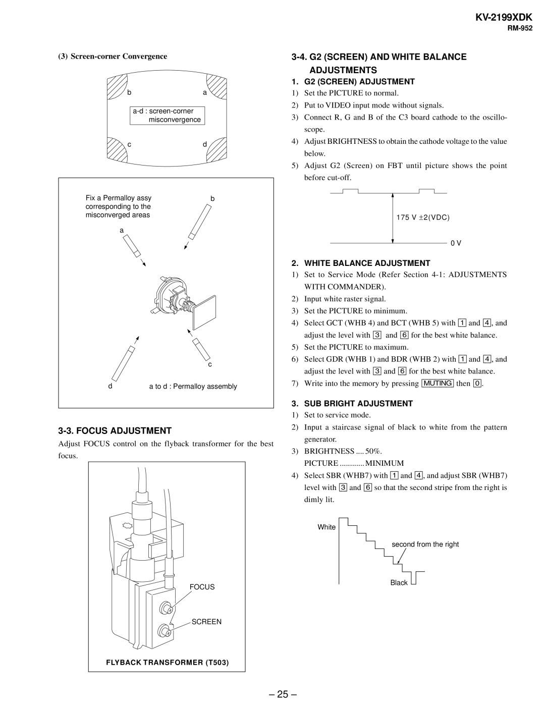
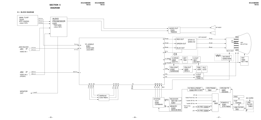
Contents Trinitron Color TV KV-2199XDK SpecificationsSET-UP Adjustments Table of ContentsDiagrams DisassemblyDiagnostic Test Indicators Self Diagnostic FunctionStopping the STANDBY/TIMER Flash Display of STANDBY/TIMER Light Flash CountHandling of SELF-DIAGNOSTIC Screen Display SELF-DIAGNOSTIC Screen Display+BÊovercurrentÊ»OCP¼ SELF-DIAGNOSTIC CircuitConnect the antenna Getting StartedInsert the batteries Into the remote Connecting optional componentsPreset the channels automatically Connecting video equipment using the ò Monitor output jacksPresetting channels Presetting channels automaticallySecuring the TV Skipping program numbers Presetting channels manuallyWatching the TV Additional tasksChanging the on-screen display language Selecting the picture and sound modes Setting the Wake Up timerSetting the Sleep timer Customizing the picture and soundChanging the favorite channel setting Viewing your favorite channelsSelecting a favorite channel Self-diagnosis function Blocking the channelsTroubleshooting TroubleshootingFront panel Identifying parts and controlsRM-952 Remote Control Rear Cover Removal Bracket Removal Chassis Assy Removal Service PositionReplacement of Parts Terminal Bracket RemovalDegauss Coil Removal Picture Tube Removal ∙ Removal of ANODE-CAP ∙ Removing ProceduresBeam Landing Section SET-UP AdjustmentsHorizontal and Vertical Static Convergence ConvergenceYCH TLV G2 Screen and White Balance Adjustments Focus AdjustmentAudio Block DiagramCircuit Boards Location Frame Schematic DiagramSecam Schematic Diagrams and Printed Wiring BoardsBoard Waveforms Power SUPPLY,HV Schematic Diagram of A2/2 board Board Printed Wiring BoardVM1 Cispr C3 Board Waveforms Printed Wiring BoardsTransistor SemiconductorsChassis Exploded ViewSection Electrical Parts List Description 1KV Diode 10ELS2N-TB5 Inductor 10MMH Carbon CMT,MELF Switch VM1 Sony