


Onboard Diagnostics
COMPUTER ENGINE CONTROLS
The Basic Engine Computer Control System
The Computer Control System consists of an
The ![]() Control System. The computer contains several programs
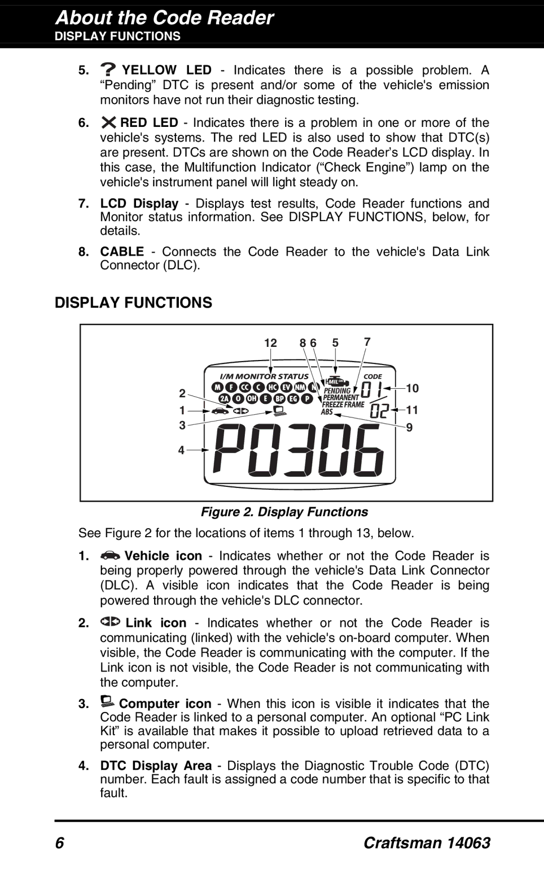
Control System. The computer contains several programs ![]() with preset reference values for air/fuel ratio, spark or
with preset reference values for air/fuel ratio, spark or ![]()
![]()
![]()
![]() ignition timing, injector pulse width, engine speed, etc.
ignition timing, injector pulse width, engine speed, etc. ![]()
![]() Separate values are provided for various driving conditions,
Separate values are provided for various driving conditions, ![]() such as idle, low speed driving,
such as idle, low speed driving, ![]() or high load. The preset reference values represent the ideal
or high load. The preset reference values represent the ideal ![]() air/fuel mixture, spark timing, transmission gear selection, etc., for any driving condition. These values are programmed
air/fuel mixture, spark timing, transmission gear selection, etc., for any driving condition. These values are programmed ![]() by the vehicle manufacturer, and are specific to each vehicle model.
by the vehicle manufacturer, and are specific to each vehicle model.
Most
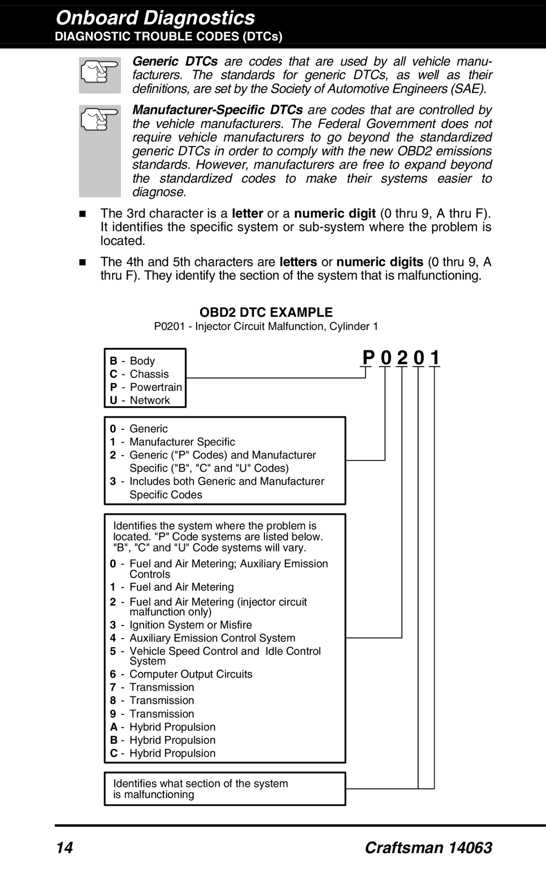
Vehicle sensors, switches, and actuators are located throughout the engine, and are connected by electrical wiring to the
The
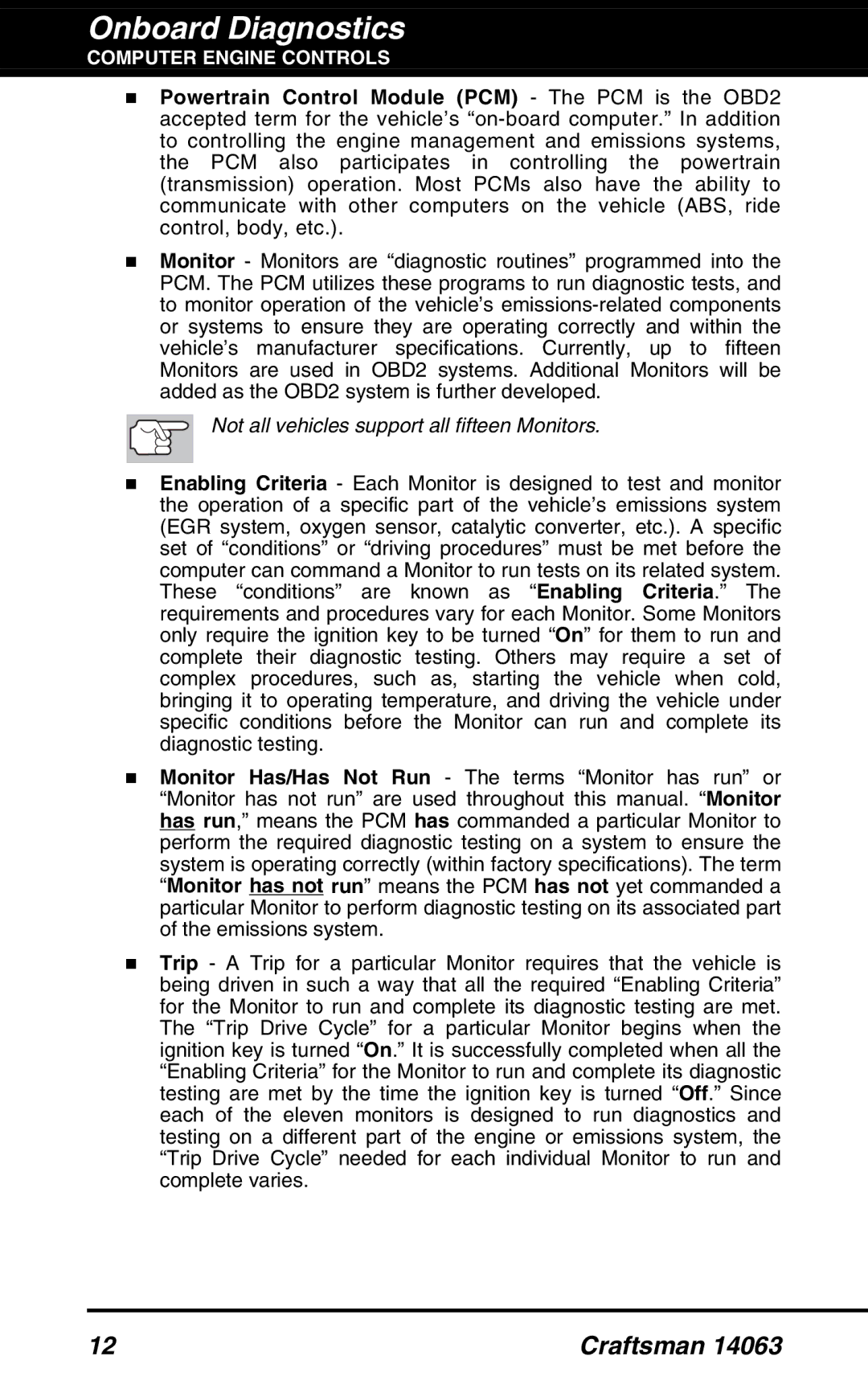
The computer compares the values received from these sensors with its preset reference values, and makes corrective actions as needed so that the sensor values always match the preset reference values for the current driving condition. The computer makes adjustments by commanding other devices such as the fuel injectors, idle air control, EGR valve or Ignition Module to perform these actions.
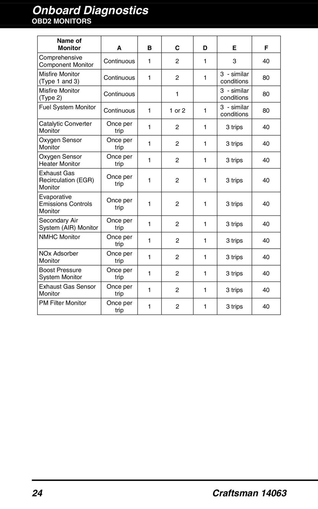
OUTPUT DEVICES
Fuel Injectors
Idle Air Control
EGR Valve
Ignition Module
Computer
INPUT DEVICES
TYPICAL COMPUTER CONTROL SYSTEM
Coolant Temperature Sensor | INPUT DEVICES |
Throttle Position Sensor | Oxygen Sensors |
Fuel Injectors |
|
Craftsman 14063 | 9 |
,