Maytag PAV2000AW*, PAV1000AW* manual Center Post Assembly

Page 44

CENTER POST ASSEMBLY

REMOVAL:

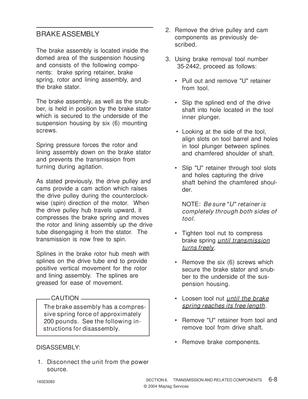
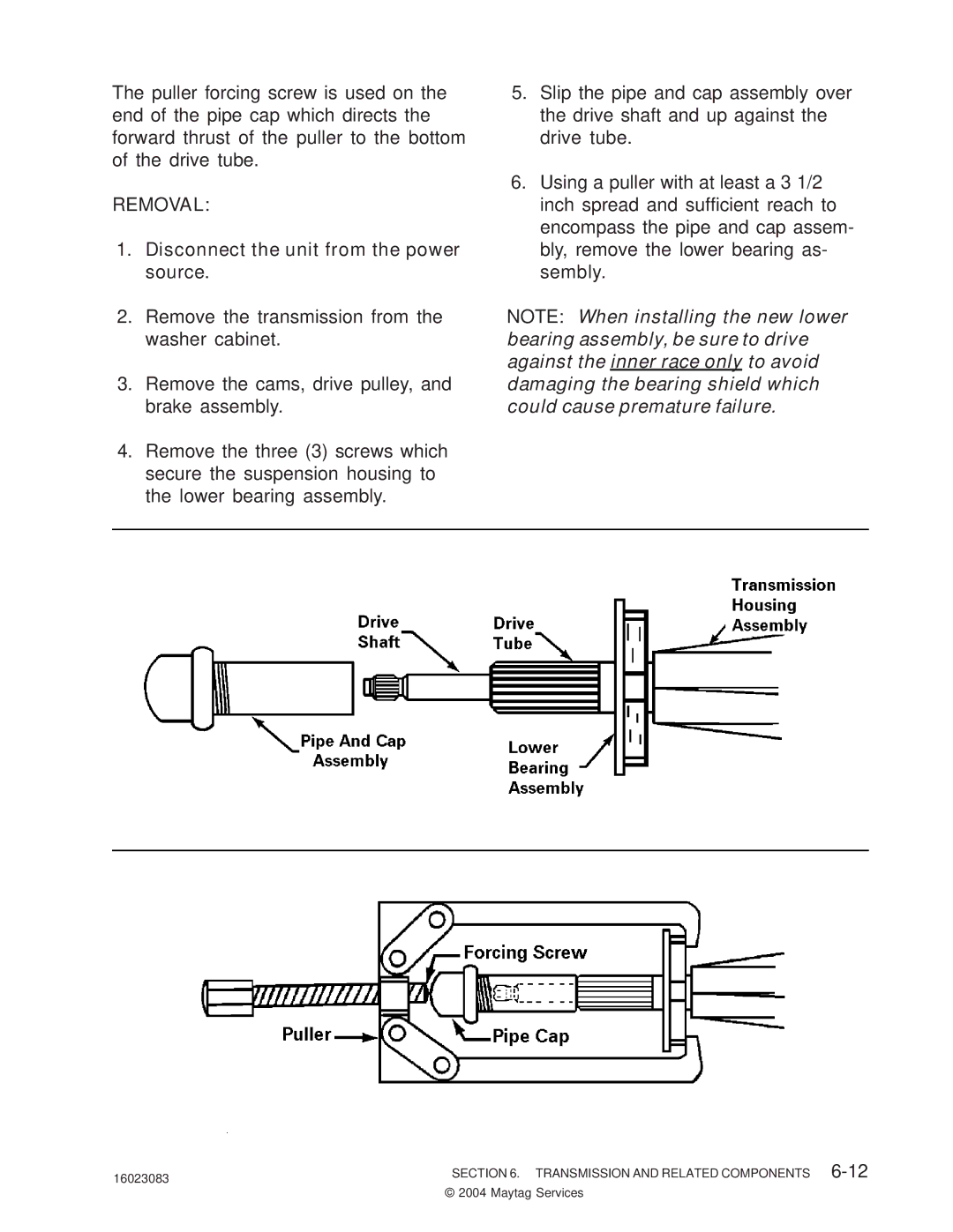
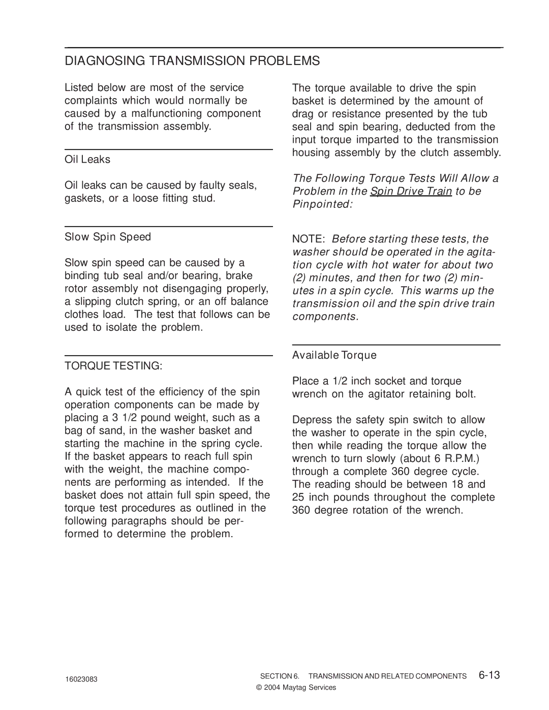
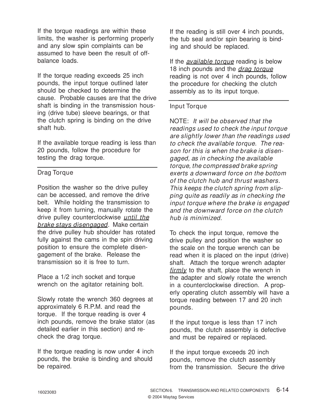
The center post assembly consists of a plastic center post. A nylon agitator bearing slips over the lower portion on the center post body.

The center post assembly is secured to the basket hub assembly by the spin basket, and to the agitator shaft. A small rubber gasket is installed in a groove on the bottom flange of the center post, and a foam gasket is placed between the bottom of the spin basket and the basket hub assembly.

The center post can be removed after removing the spin basket, and the agita- tor shaft "O" ring.

BEARING AND SEAL HOUSING

The die-cast bearing and seal housing slips over a machined area on the lower drive tube. The basket hub assembly threads downward over the drive tube and secures the bearing and seal hous- ing.

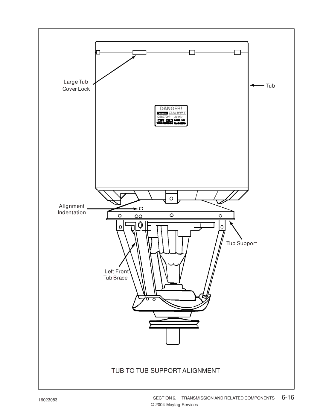
The spin bearing and the tub seal are installed in a cavity in the center of the housing. The sheet metal tub support is attached to the under side of the housing with three (3) mounting screws. The spin bearing has been pressed into the underside of the housing cavity and is secured by the tub support.

The center of the tub assembly mounts to the upper flange of the housing with a tub gasket and a tub seal installed between.

The bottom of the tub sits on, and is attached to, the tub support.

1.Disconnect the unit from the power source.

2.Remove the agitator, spin basket, tub assembly, and center post.

3.Remove the Seal nut with 2202898 and 35-2968

4.Remove the basket hub assembly by turning it in a counterclock- wise direction, using tool number 35-2968.

5.Remove the suspension springs to prevent damage to the tub braces and unbolt the tub braces from the tub support.

6.To remove, lift up on the bearing and seal housing with tub support attached.

7.To disassemble tub support from housing, remove mounting screws from underside.

16023083

SECTION 6. TRANSMISSION AND RELATED COMPONENTS 6-2


© 2004 Maytag Services

Image 44
Contents 16023083 16023083 Introduction 16023083 Introduction Maytag Corporation Contents Transmission and Related Components Safety Notes 16023083 Safety Notes Maytag Corporation Specifications Agitator Speed Special Tools 16023083 Special Tools Maytag Corporation 16023083 16023083 16023083 16023083 16023083 16023083 16023083 16023083 16023083 16023083 16023083 16023083 16023083 16023083 16023083 16023083 16023083 16023083 16023083 16023083 16023083 16023083 16023083 16023083 16023083 16023083 16023083 16023083 16023083 16023083 Transmission and Related Components Center Post Assembly TUB Seal Spin Bearing Drive Pulley and Cams Original Thrust Washer Design See following figure Brake Assembly Min Pulley Hub Reference Max Pulley Hub Reference Cam Arrow Transmission and Related Components Transmission Housing Assembly Removal Diagnosing Transmission Problems Drag Torque See the illustration on TUB to TUB Support Alignment 16023083 16023083 16023083 16023083 16023083 16023083 16023083 16023083 16023083 16023083 16023083 16023083 16023083 16023083 16023083 16023083 16023083 Wiring Information 16023083 Wiring Information Wiring Information Switch and Timer Sequence Wiring Information PAV3300 Wiring Information SWITCH35-6345CONTROLB Schematic PAV5157, PAV5158 Wiring Information PAVT344 Wiring Information HAV2460 Wiring Information PAVT244 Wiring Information PAVT234, HAV2360, MAV2200 Wiring Information HAV2557/2558 Wiring Information HAV3460 Wiring Information PAVT444, HAV4657 16023083 16023083 16023083 16023083 16023083 16023083 16023083 16023083 16023083 Troubleshooting 16023083 Temperature Control Board PIN Source OUTPUT/INPUT 16023083