Chapter 2 PEM Faults and Fan Assembly Failures
Fan Assembly Module Faults
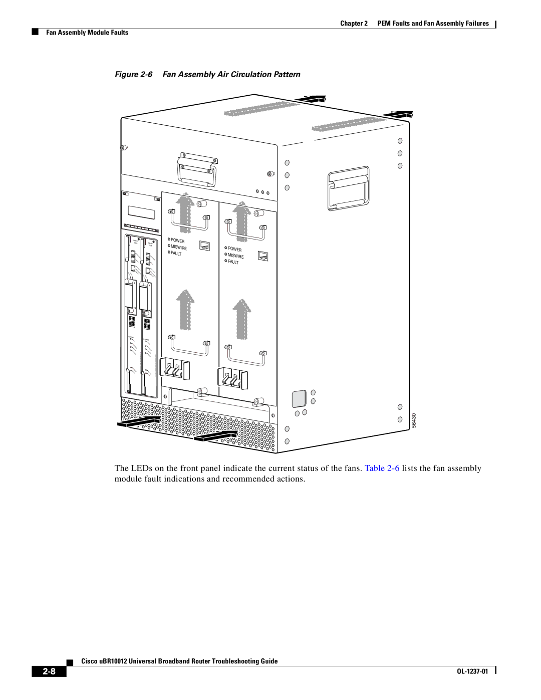
Figure 2-6 Fan Assembly Air Circulation Pattern
SLOT |
|
SLOT | |
0 | 1 |
CISCO |
|
10000 | CISCO |
| 10000 |
CO |
|
NS |
|
OC
LOE
|
| NS | |
|
| OL | |
A |
|
| E |
UX |
|
|
|
|
| A |
|
|
| UX |
|
A |
|
|
|
CTI |
|
|
|
VIT | A |
| |
ET | Y | CT |
|
HE |
| IV | |
LI RN | E ITY | ||
NK ET | TH |
| |
|
| L ER | |
| SLOT | IN | N |
| SLOT | K | ET |
| 0 1 |
|
|
PO |
| |
WER |
| |
MISWIRE | PO | |
FA | WER | |
M | ||
ULT | ||
| ISWIRE | |
| FAULT |
ALARMS |
|
A |
|
CO |
|
C |
|
RIT |
|
IC | |
M | AL |
AJ |
|
OR | |
M |
|
IN |
|
OR | |
S |
|
TA |
|
TU | |
F | S |
AIL |
|
PERFORMANCE ROUTING ENGINE
ALARMS |
|
A |
|
CO |
|
C |
|
RIT |
|
IC | |
M | AL |
AJ |
|
OR | |
M |
|
IN |
|
OR | |
S |
|
TA |
|
TU | |
F | S |
AIL |
|
PERFORMANCE ROUTING ENGINE
56430
The LEDs on the front panel indicate the current status of the fans. Table
Cisco uBR10012 Universal Broadband Router Troubleshooting Guide
|
| |
|