Chapter 2 PEM Faults and Fan Assembly Failures
Other Electrical Problems
The power shelf includes three
During normal operation, the three
Faults on the 2400W
•The
•The AC power plug to one or more power modules has been removed or unplugged.
•One or more power modules has failed and must be replaced.
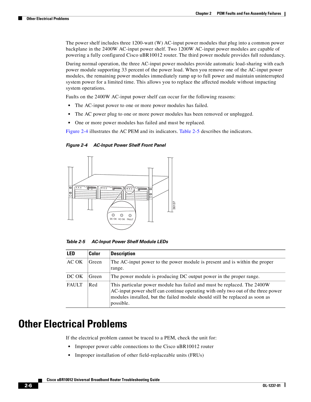
Figure 2-4 illustrates the AC PEM and its indicators. Table 2-5 describes the indicators.
Figure 2-4 AC-Input Power Shelf Front Panel
DC OK AC OK FAULT
DC OK AC OK FAULT
DC OK AC OK FAULT
|
| 36137 |
|
| DC OK AC OK FAULT |
Table | ||
|
|
|
LED | Color | Description |
|
|
|
AC OK | Green | The |
|
| range. |
|
|
|
DC OK | Green | The power module is producing DC output power in the proper range. |
|
|
|
FAULT | Red | This particular power module has failed and must be replaced. The 2400W |
|
| |
|
| modules installed, but the failed module should still be replaced as soon as |
|
| possible. |
|
|
|
Other Electrical Problems
If the electrical problem cannot be traced to a PEM, check the unit for:
•Improper power cable connections to the Cisco uBR10012 router
•Improper installation of other
Cisco uBR10012 Universal Broadband Router Troubleshooting Guide
|
| |
|