Chapter 4 Troubleshooting Line Cards
Troubleshooting the Timing, Communication, and Control Plus Card
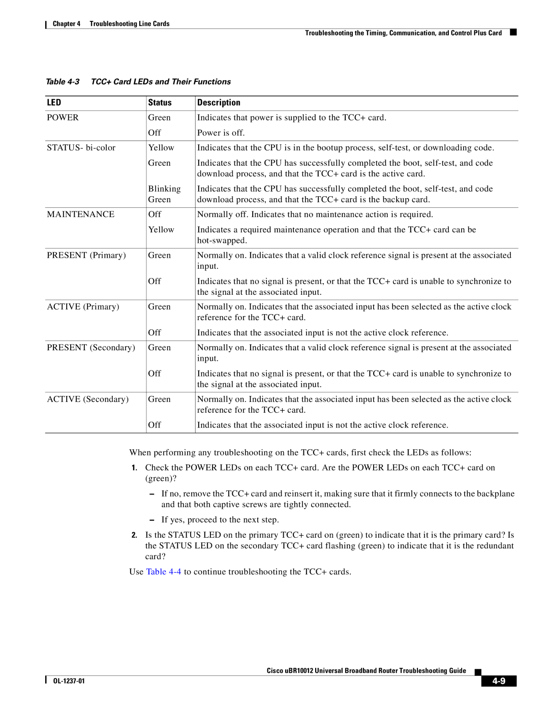
Table
LED | Status | Description |
|
|
|
POWER | Green | Indicates that power is supplied to the TCC+ card. |
| Off | Power is off. |
|
|
|
STATUS- | Yellow | Indicates that the CPU is in the bootup process, |
| Green | Indicates that the CPU has successfully completed the boot, |
|
| download process, and that the TCC+ card is the active card. |
| Blinking | Indicates that the CPU has successfully completed the boot, |
| Green | download process, and that the TCC+ card is the backup card. |
|
|
|
MAINTENANCE | Off | Normally off. Indicates that no maintenance action is required. |
| Yellow | Indicates a required maintenance operation and that the TCC+ card can be |
|
| |
|
|
|
PRESENT (Primary) | Green | Normally on. Indicates that a valid clock reference signal is present at the associated |
|
| input. |
| Off | Indicates that no signal is present, or that the TCC+ card is unable to synchronize to |
|
| the signal at the associated input. |
|
|
|
ACTIVE (Primary) | Green | Normally on. Indicates that the associated input has been selected as the active clock |
|
| reference for the TCC+ card. |
| Off | Indicates that the associated input is not the active clock reference. |
|
|
|
PRESENT (Secondary) | Green | Normally on. Indicates that a valid clock reference signal is present at the associated |
|
| input. |
| Off | Indicates that no signal is present, or that the TCC+ card is unable to synchronize to |
|
| the signal at the associated input. |
|
|
|
ACTIVE (Secondary) | Green | Normally on. Indicates that the associated input has been selected as the active clock |
|
| reference for the TCC+ card. |
| Off | Indicates that the associated input is not the active clock reference. |
|
|
|
When performing any troubleshooting on the TCC+ cards, first check the LEDs as follows:
1.Check the POWER LEDs on each TCC+ card. Are the POWER LEDs on each TCC+ card on (green)?
–If no, remove the TCC+ card and reinsert it, making sure that it firmly connects to the backplane and that both captive screws are tightly connected.
–If yes, proceed to the next step.
2.Is the STATUS LED on the primary TCC+ card on (green) to indicate that it is the primary card? Is the STATUS LED on the secondary TCC+ card flashing (green) to indicate that it is the redundant card?
Use Table
Cisco uBR10012 Universal Broadband Router Troubleshooting Guide
|
| ||
|
|