Table of Contents |
|
Part Locations and Removal | 3 |
Lower Front Panel Removal | 3 |
Upper Front Panel Removal | 3 |
Top Cover Removal | 3 |
Lint Box/Blower Assembly Removal | 4 |
Gas Valve/Ignition System Removal | 5 |
Oven Chamber Removal | 5 |
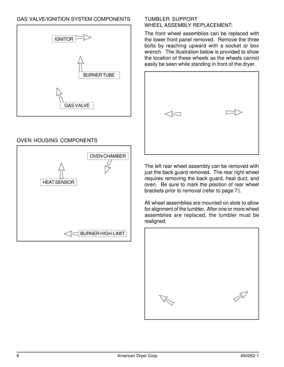
Gas Valve/Ignition System Components | 6 |
Oven Housing Components | 6 |
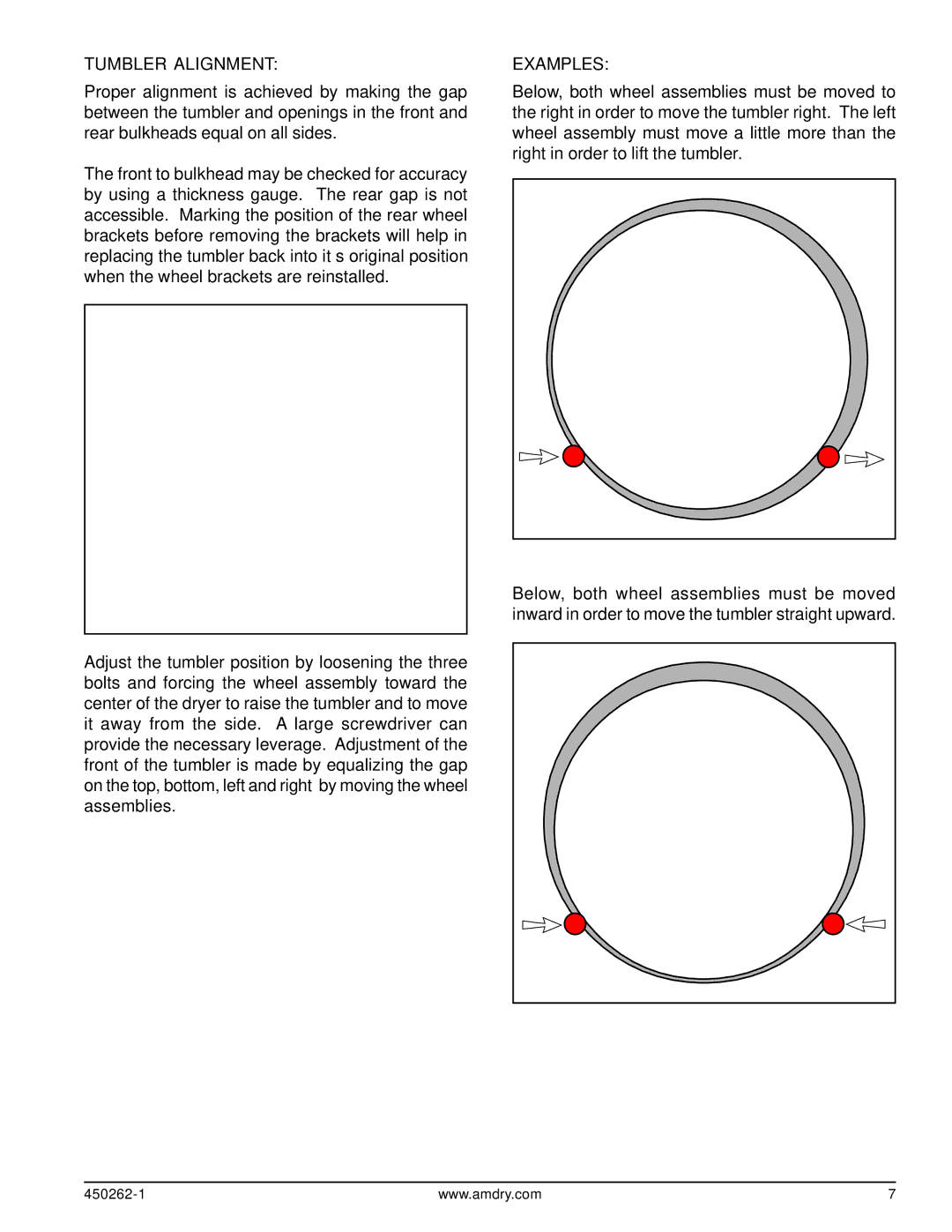
Tumbler Support Wheel Assembly Replacement | 6 |
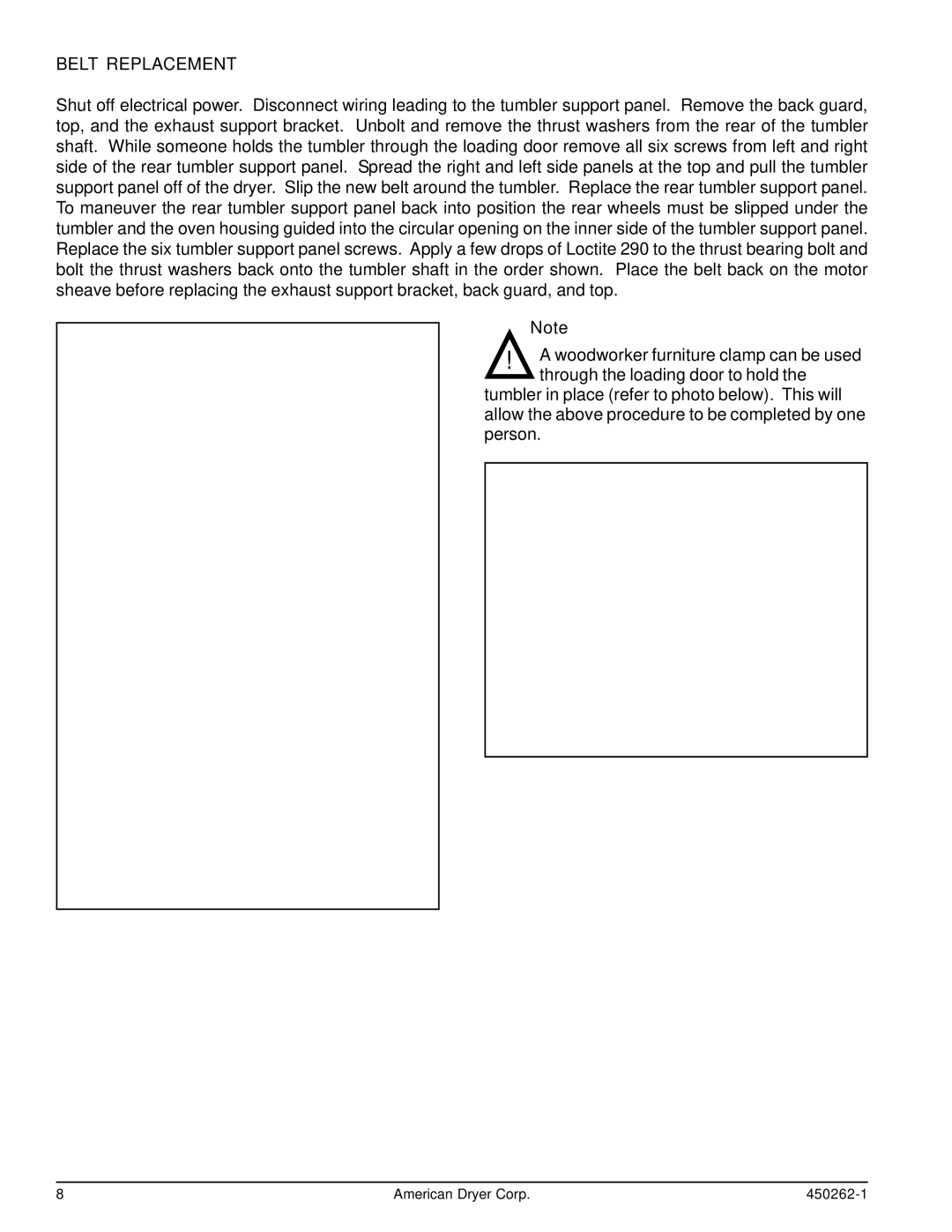
Tumbler Alignment | 7 |
Belt Replacement | 6 |
Placing the Belt Back on the Motor Sheave | 9 |
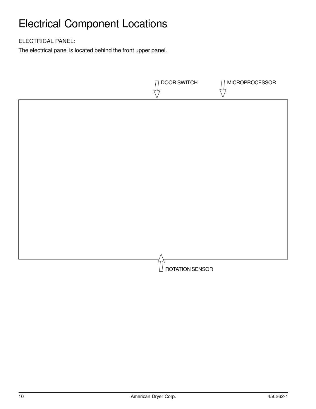
Electrical Component Locations | 10 |
Electrical Panel | 10 |
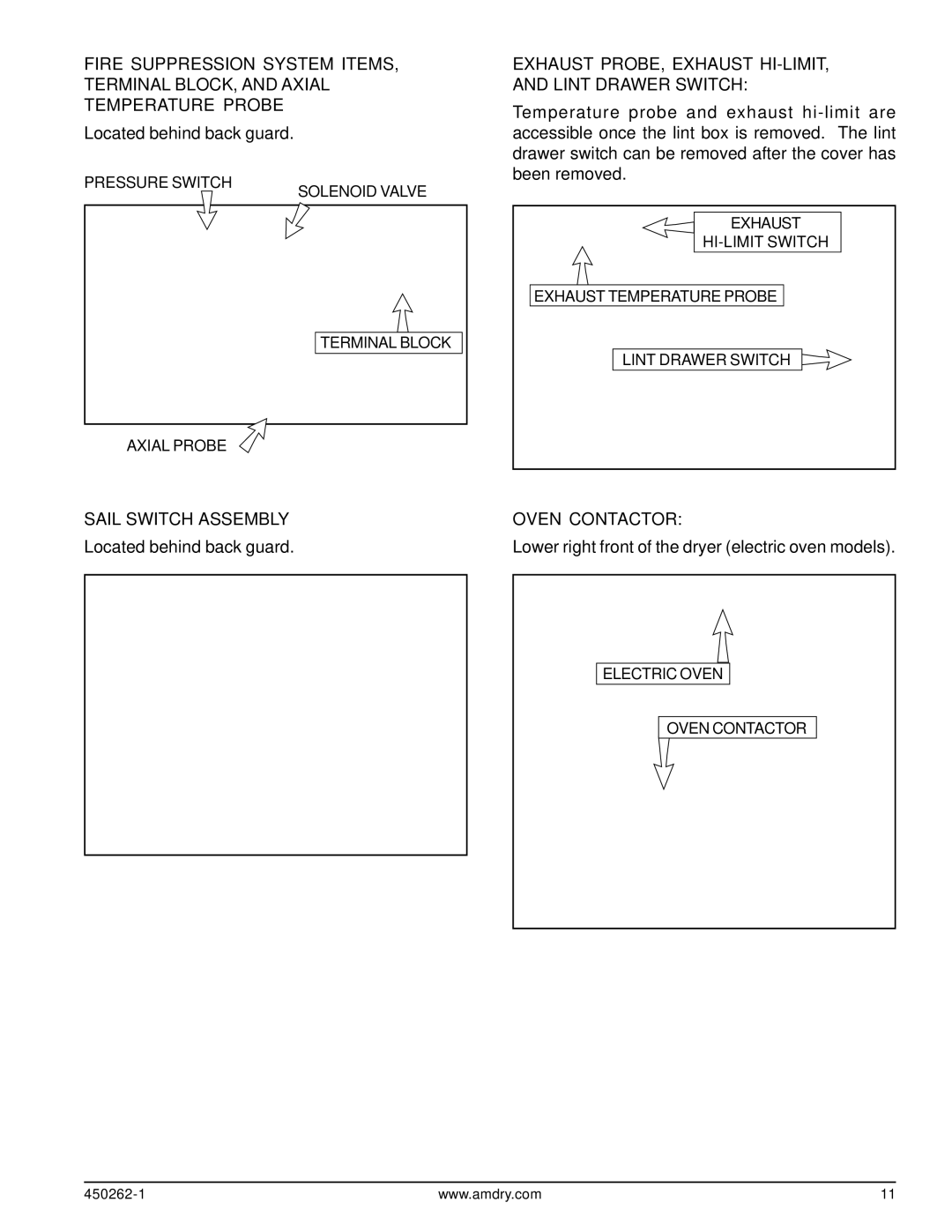
Fire Suppression System Items, Terminal Block, |
|
and Axial Temperature Probe | 11 |
Sail Switch Assembly | 11 |
Exhaust Probe, Exhaust | 11 |
Oven Contactor | 11 |
We have tried to make this manual as complete as possible and hope you will find it useful. ADC reserves the right to make changes from time to time, without notice or obligation, in prices, specifications, colors, and material, and to change or discontinue models. The illustrations included in this manual may not depict your particular dryer exactly.
