Humminbird Wide View manual

Page 24

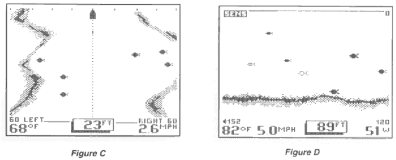
If you are using the Wide Side accessory transducer, the screen layout will look like Figure C.

Later, you will learn of another feature called "advanced operation". This feature uses yet another screen layout as shown in Figure D which maximizes the display for the terrain and target presentation.

The number of vertical pixels (picture elements or dots) in a given depth range

determines the display resolution, or ability to differentiate targets close to the bottom or other targets. The Wide View is capable of distinguishing between targets only 6 inches apart, and show fish within 6 inches of the bottom.

On all screens but the Wide Side view, the horizontal line at the top of the display is the "Zero" line. This represents the surface of the water. The "Zero" line will always have a gap which moves as the screen updates. This gap lets you know that the display is updating even if the bottom terrain remains the same or is not visible on the selected depth range. The farthest right column of information is the most recent information, and it shows what is directly under your boat.

At power-up, the Wide View locates the bottom and adjusts the depth range to a setting most appropriate for that depth. The bottom will be usually shown about 2/3 of the way down the display. The Structure ID depiction of the bottom may appear differently in different situations. If the bottom is very hard and smooth, the bottom depiction will be narrow and dense. If the bottom is mud or soft sand, the bottom depiction will be thick and less dense. This indicates that much of the sonar signal is absorbed by the soft bottom. If the bottom is rugged and varying, such as a rocky bottom, the depiction will be textured and vary in density. Structure, such as submerged trees or brush, or other objects are clearly displayed above the solid bottom return, in varying densities of pixelization. This bottom depiction is useful in locating structure, by comparing relative density as well as depth.

Image 24
Contents Page Accessories Installation OverviewParts Supplied Determining How to Mount the Transducer Alternate Transducers and Mounting Methods Portable MountingTrolling Motor Mounting Thru-Hull MountingBeginning Installation Transducer ExchangeTransom Installation Step One Determine Where to Mount the TransducerStep Two Drill the Mounting Holes Step Three Assemble the TransducerPage Step Five Adjust the Running Position of the Transducer Step Four Mount the Transducer to the TransomConfirm the pivot angle has not changed Page Step Six Route the Cable Inside the Hull Installation Step One Determine the Mounting LocationStep Two Test the Mounting Location Page Step Three Permanently Mount the Transducer Control Head Installation Step One Determine Where to MountStep Two Connect the Power Cable to the Boat Page Step Three Drill the Mounting Holes Step Four Run the CablesPage Step Five Assembling the Connector Holder Your Humminbird is now ready for operationTest the Installation Testing the Installation Using the Wide View Page Page Page Control Functions Transducer Page Sensitivity Page Range ZoomPage Bottom Alarm Fish AlarmPage TripLog System Options Page Advanced Features Wide Side OperationPage