Kenwood manual SPS separate power sources TS-480HX only, SPS schematic diagram

Page 10

SPS (separate power sources) [TS-480HX only]

SPS is shorthand for “operating at 200W using two 100W 13.8V power sources.” To generate a 200W output from 13.8V requires a maximum (total) current of 41A. As previously explained, the TS-480HX employs a pair of 100W final amps. What the SPS design does is to supply these amps from two separate power supplies, as shown in Fig. 3 below.

The use of two power supplies may appear inconvenient, but in actual fact this arrangement is quite practical. Many customers already possess a 100W class power supply, so when they acquire this 200W transceiver they do not have to make an additional purchase of a new 200W class power supply. It is possible for them to make use of the 100W unit in their possession.

The PS-53 power supply is specified for the TS-480; however, as long as it can produce 20.5A or more continuously at 13.8V, other power supplies can be used. Also, it is possible to operate this transceiver using a single power supply that can produce at least 41A continuously; note, however, that two power cables would still be needed.

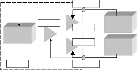
Fig. 3: SPS schematic diagram

DC1 connector

Drive amp

Other circuits

Final amp 1

Final amp 2

DC power

supply 1

(13.8V, ≥20.5A)

DC power

supply 2 (13.8V, ≥20.5A)

Chassis

DC2 connector

10

Image 10
Contents Page TS-480HX TS-480SAT Determination to create a unique transceiver Design ObjectivesBack to basics The appeal of HF lies in DX’ing Focus on basic performance Standalone control panel200W challenge Adding appeal to fixed station operations Overview of the TS-480 SeriesTS-480 concept began with development of the TS-570? Development Objectives for the TS-480 SeriesAchieving 200W output in a compact transceiver Focusing on HF Circuitry TX circuits 200W final sectionTX IMD output 200W SPS separate power sources TS-480HX only SPS schematic diagram100W final section Failsafe device some TS-480HX versions onlyAntenna tuner TS-480SAT 200W final section FM modulation block diagram FM circuitRX circuitry Front end RX 1st mixerRX dynamic range RX sensitivity Jumpers for joy Circuitry after the roofing filter Comparison of optional CW filters 500HzOption installation unit Features useful for mobile operations Auxiliary FeaturesFeatures useful for 50MHz operations Full compatibility with digital modes data modesNew 5MHz band DSP circuit Features of the Built-in DSPIdeal for mobile operations DNL Noise reduction Demonstrates how ignition noise is reduced by the DNLNR OFF Beat cancel BC OFFRX DSP filters Switching Width During CW operations RX equalizer & TX equalizer CW auto tuneTips TS-480 menusDSP Useful if you want to go on to tune FSK APO Functions that can be assigned to PF keys Assigned Use Split Making menus easier to use Menu switching Quick menuStructural Features Internal structure of the main unitCooling diagram CoolingUpper side Temperature rise around final transistors Page Design concept Constant recording function New Option Voice Guide & Storage Unit VGS-1Message recording/playback function Menu settings Split mode ResetConfiguration mode for TX output, etc Voice GuideMemory channel Other featuresVFO mode, direct frequency entry Variable Voice Guide speedKNS added Main functionsButton layout & basic operation Changing memory and registered details CW keyingCompatibility with KNS Kenwood Network Command System Reading and writing filesSetting up KNS on the Arcp side Accidental continuous TXPage Using a broadband router Checking LAN settings New Option ARHP-10 Amateur Radio Host Program FreewareAdjust PC volume User setupPage Troubleshooting Network & Operations Problem SolutionCannot get KNS to work Sound Problem Solution Connect a microphone to the computer and bring up TS-480 In-Depth Manual