Furuno 841 MARK-2 manual Echo Trails, Navigation Data Display

Page 28

2.21 Echo Trails

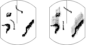
You can show the trails of targets in after- glow. This function is useful for alerting you to possible collision situations.

Starting echo trail

Press the [TRAIL] key to start the echo trail function. Afterglow starts extending from targets and "TRAIL" and the echo trail time appear at the top right-hand corner of the display. Press the key again within 3 sec- onds to select a different trail time, among 15 sec, 30 sec, 1 min, 3min, 6 min, 15 min, 30 min, and continuous. In continuous plot- ting the time elapsed appears at the top right corner on the display.

Note: If the range is changed, trails are painted anew with the newly selected range.

minutes and 59 seconds. When the elapsed time clock counts up to that time the elapsed time display is reset to zero all trails are erased and then trailing is restarted.

Adjusting brilliance of afterglow

The brilliance of the trails' afterglow can be set on the Backlight/Brilliance menu.

1)Press the [MENU] key.

2)Select Backlight/Brilliance and press the [ENT] key.

3)Select Echo Trails.

4)Select brilliance.

5)Press the [ENT] key followed by the [MENU] key.

Canceling echo trails

True trails

Relative trails


(requires gyro)

Figure 2-17 Appearance of echo trails

Fixed time trails

When the elapsed time clock counts up to the trail time selected, the elapsed time dis- play freezes. The oldest portions of trails are erased so only the latest trail, equal in length to the trail time selected, is shown. Then, trails start extending again. For example, the one minute trail time is selected. When the elapsed time display freezes at 60 seconds, all but the latest one minute of trails are erased and then trailing continues.

Continuous trail

The maximum continuous trail time is 99

Press the [TRAIL] key to erase the TRAIL indication.

2.22The Navigation Data Display

Navigation data can be displayed at the screen bottom if this radar receives naviga- tion input in NMEA 0183 format. Naviga- tion data includes

position in latitude and longitude or Lo- ran-C time differences (TDs)

bearing and range to a waypoint selected on the navigator

cross track error (XTE—the amount in nautical miles and the direction the ves- sel if off course)

depth

speed.

If the navigation data include the destina- tion data, waypoint position is denoted on the radar display by a dashed ring.

16

Image 28
Contents Marine Radar B . N o . O M E 3 4 4 4 Safety Instructions Do not open the equipment Stay away from transmitting antennaDo not disassemble or modify the equipment Do not operate the equipment with wet handsIii Use the correct fuseTable of Contents Features ForewordSpecifications Antenna UnitTransceiver Module contained in radome Display UnitInterface Nmea Installation Materials CP03-15xx Accessories FP03-05900Equipment List Complete SetOptional Equipment Configuration Model 841 MARK-2Principle of Operation How radar works Operation Control DescriptionDisplay Indications and Markers Turning the Radar On and Off5NM 675NM 220.9R 0.646NM 308.7RAdjusting LCD Backlighting and Display Tone Adjusting Control Panel BrillianceTransmitting Selecting the RangeGeneral procedure Adjusting GAIN, STC, A/C Rain and FTCSTC MAN Auto Tuning the Receiver Adjusting A/C RainAdjusting FTC How to tune manuallyMeasuring the Range Measuring the BearingPress the Menu key to open the menu. The main menu appears Menu OperationSee the table on the next Menu description Menu FunctionSelecting the Display Mode 11 Display modesSelecting the Presentation Mode Window DisplayCourse-up, you may select CU or WPT- UP, on the menu CU course-upGuard Alarm Setting the guard zoneSilencing the audible alarm WPT-UP waypoint-upCanceling the guard zone Suppressing Radar InterferenceOff Centering the Display Suppressing Noise InterferenceSelecting Pulselength Echo Trails Navigation Data DisplaySetting up the nav data display Echo Stretch magnifying long range echoesPress the Menu key Select Nav Data and press the ENT key Turning echo stretch on or offSelecting Unit of Measurement for Range Selecting Bearing ReferenceWatchman Turning on watchmanCanceling watchman Erasing the Heading MarkerDeselecting Ranges Displaying Navigation Data During Stand-byVisual Alarm Indications Error Visual alarmOutputting Cursor Position to Navigator Displaying Cursor Position, Range and Bearing to CursorInterpreting the Display Radar Wave and Radar HorizonTarget Properties and Radar Wave Reflection Super-refractionBearing Resolution Range ResolutionFalse Echoes Multiple echoesSide-lobe echoes Indirect echoesNautical Chart and Radar Picture Maintenance & Troubleshooting Safety InformationReplacing the Fuse Preventative MaintenancePeriod Check point Remarks Troubleshooting But ThenSelf Test Self TestSiting, handling considerations Antenna Unit InstallationMounting Holes for antenna unit Parallel with the fore and aft lineDisplay Unit Installation Mounting considerationsMounting procedure Display unit is designed to be mounted on a tabletopSignal cable connection ConnectionsTo connect external equipment to the OP- Tion connector For E/SNavigation aid, video sounder connection Heading Sensor ConnectionInstallation Check List RadarDisplaying the Installation Menus Initial Adjustment of PictureFollow the procedure below to obtain proper radar picture Relative Bearing Alignment Entering Initial SettingsSweep Timing Closing the Installation Menus Press the Menu key and turn off the powerPage Page Page Page Page Page