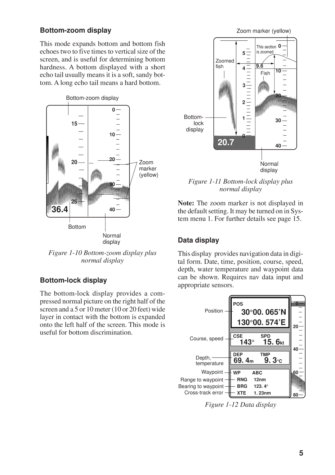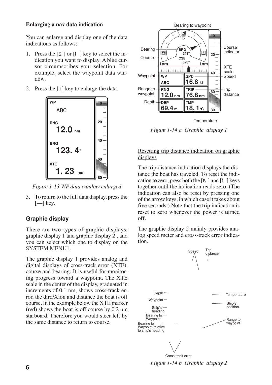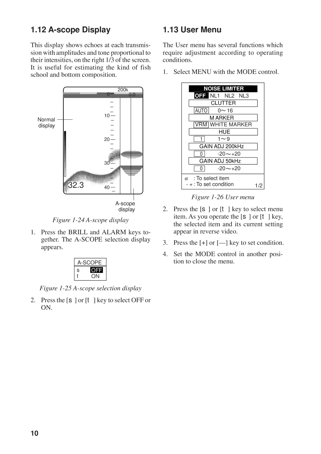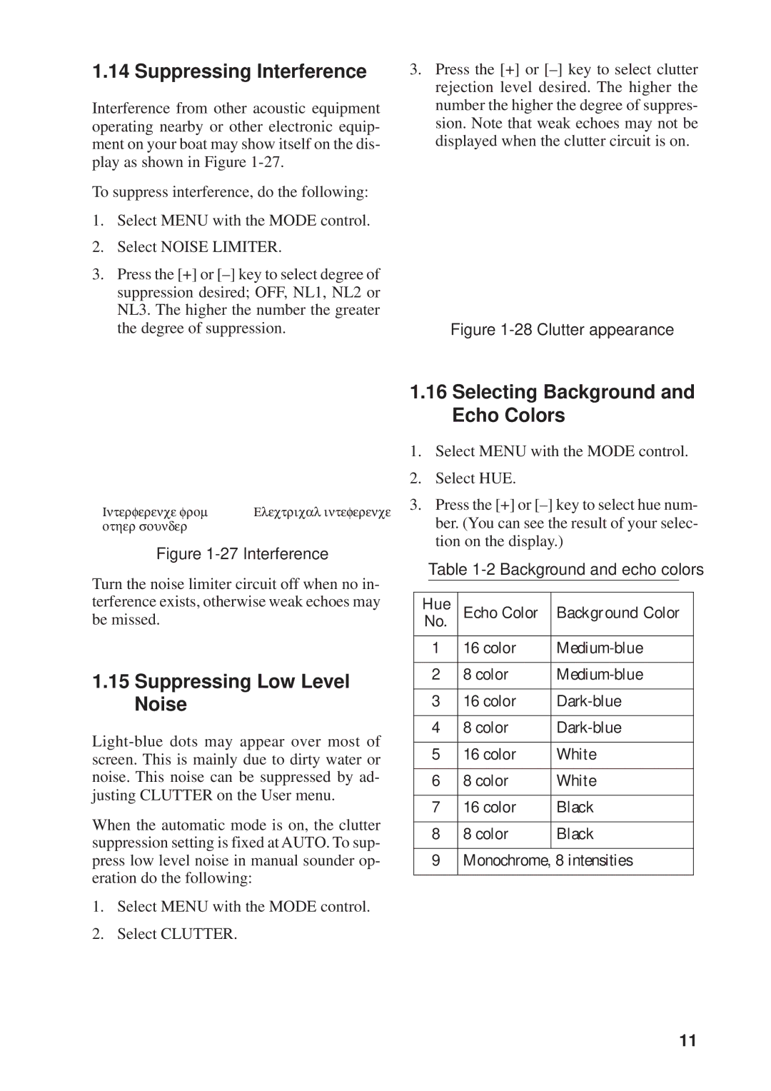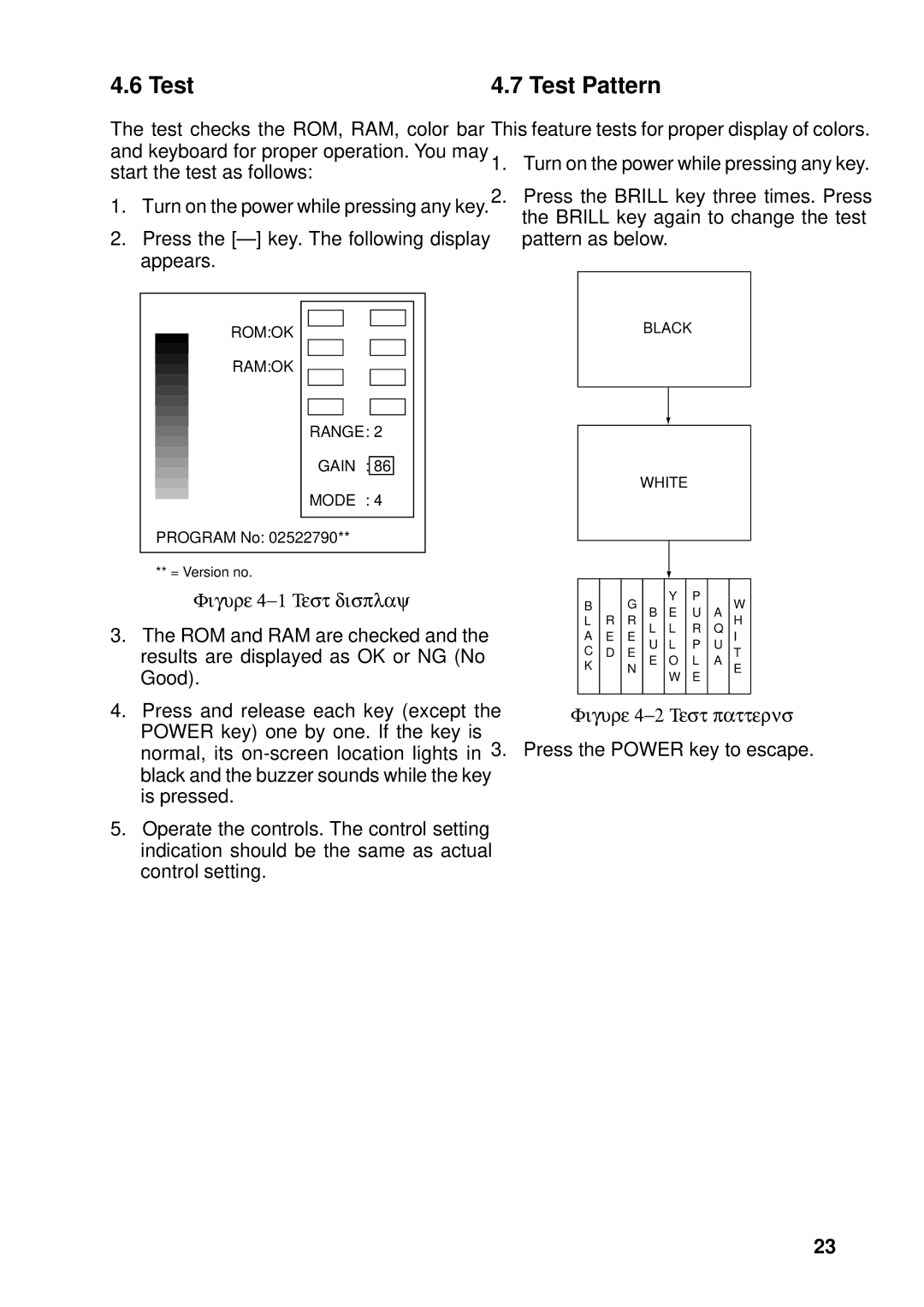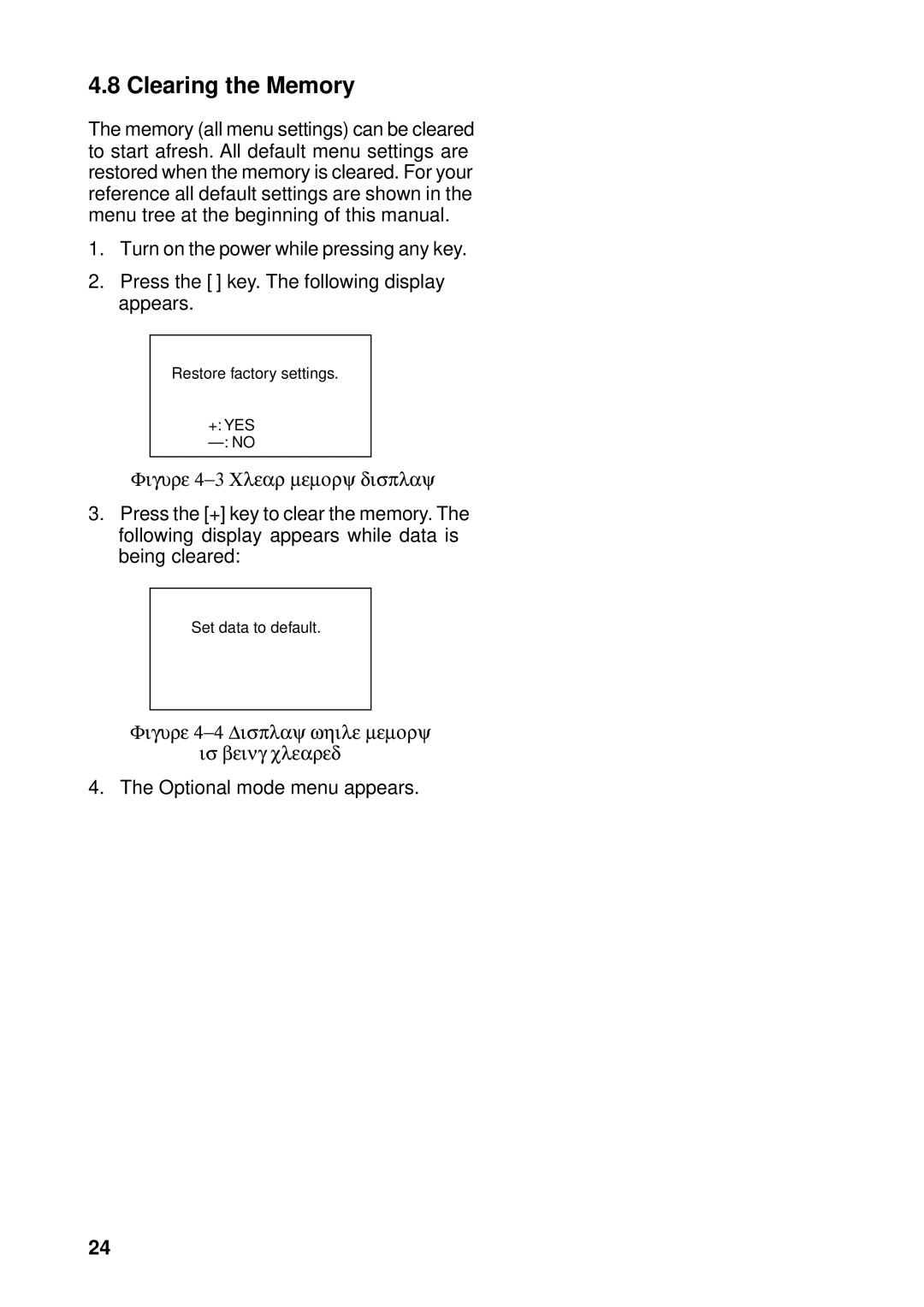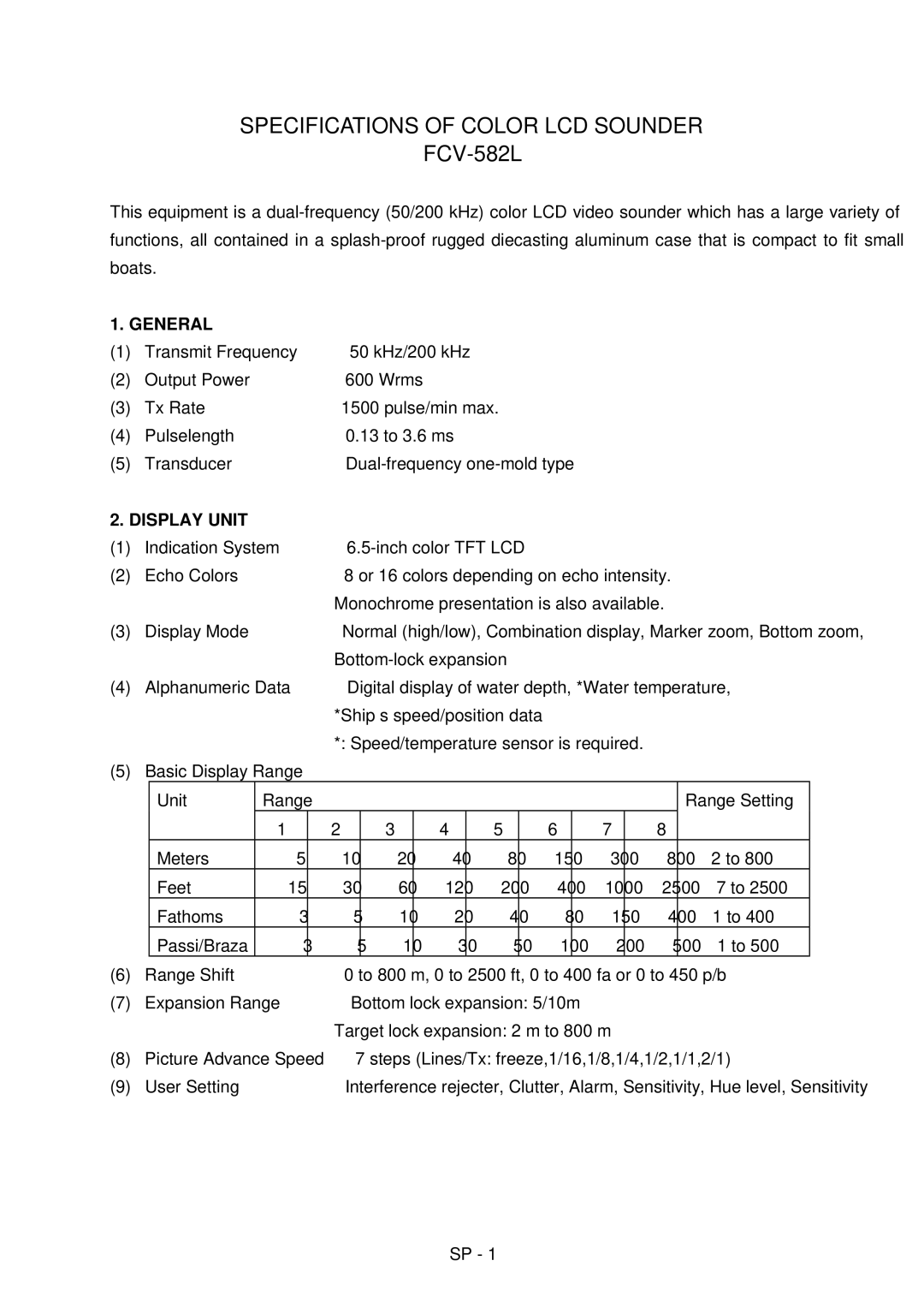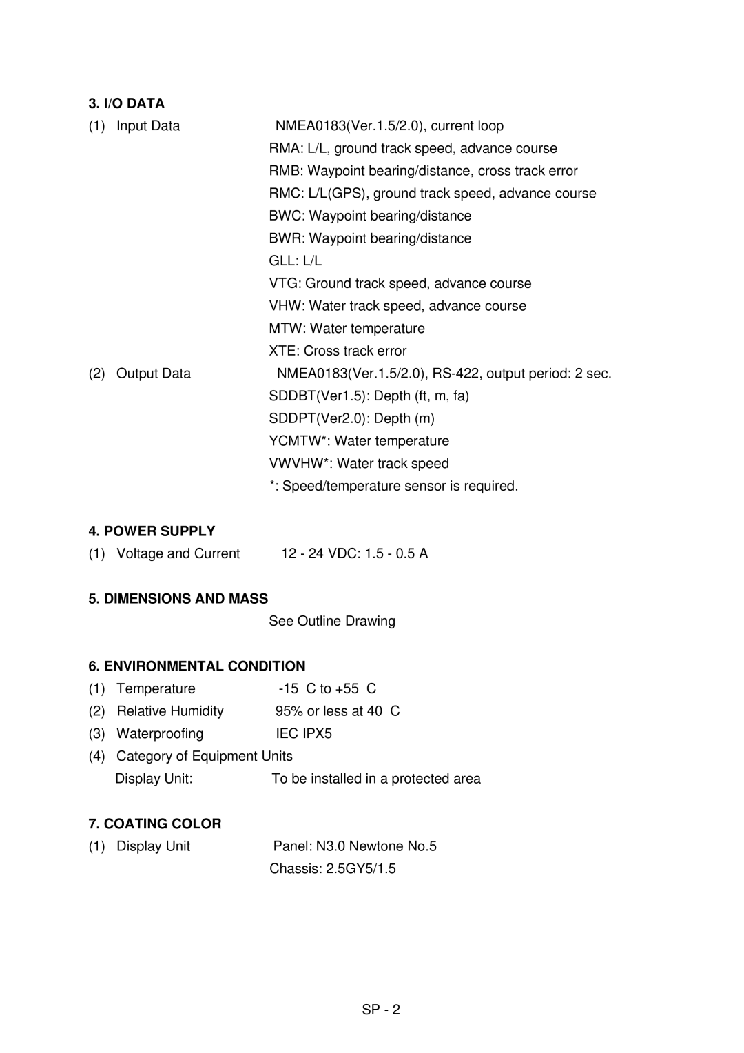
Selecting data or graphic display
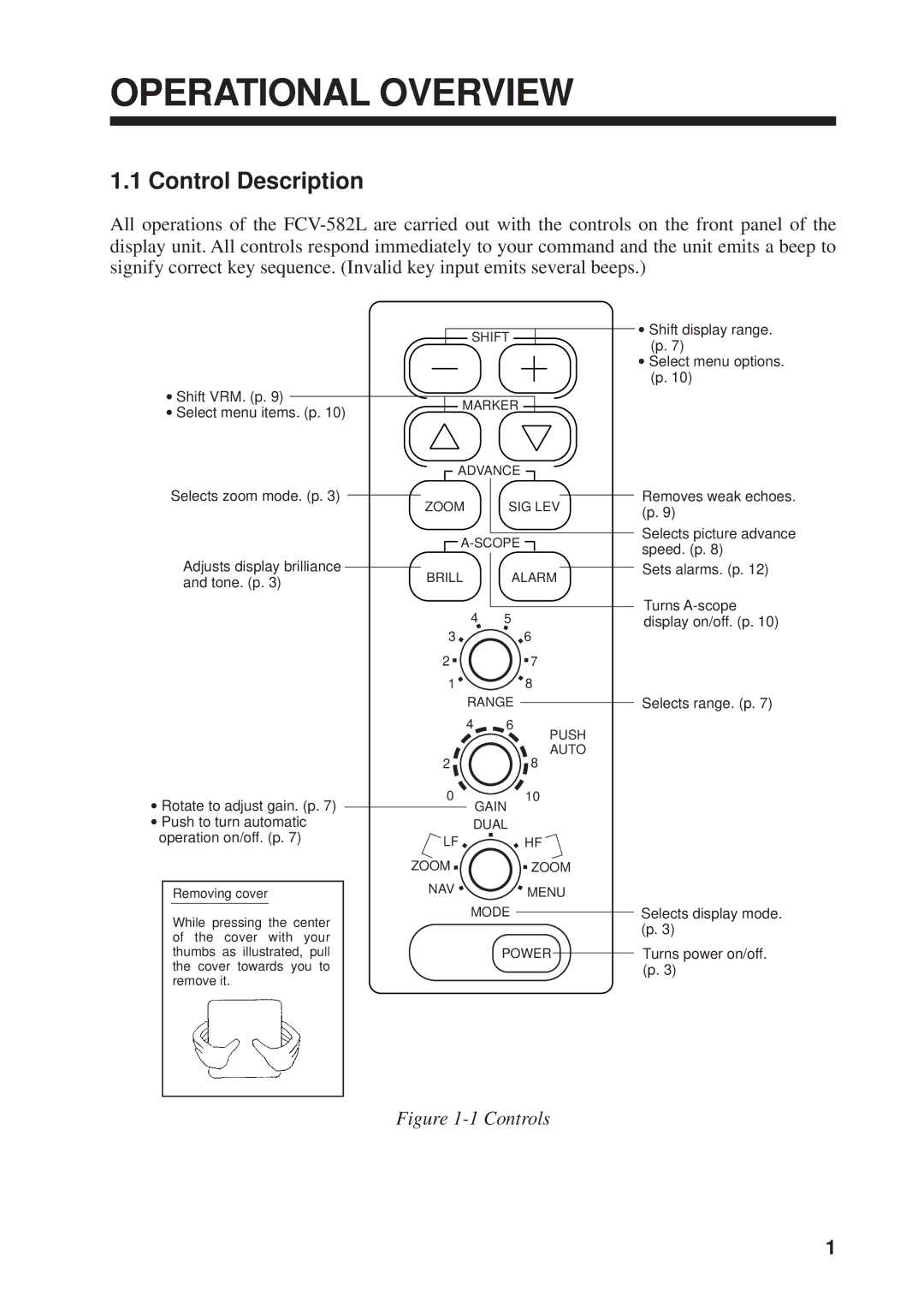
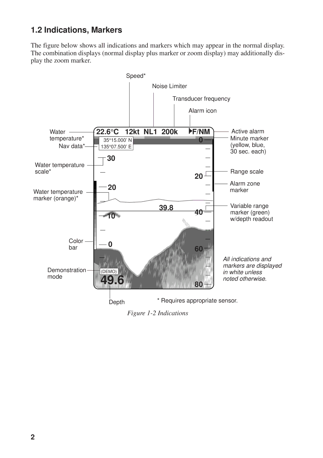
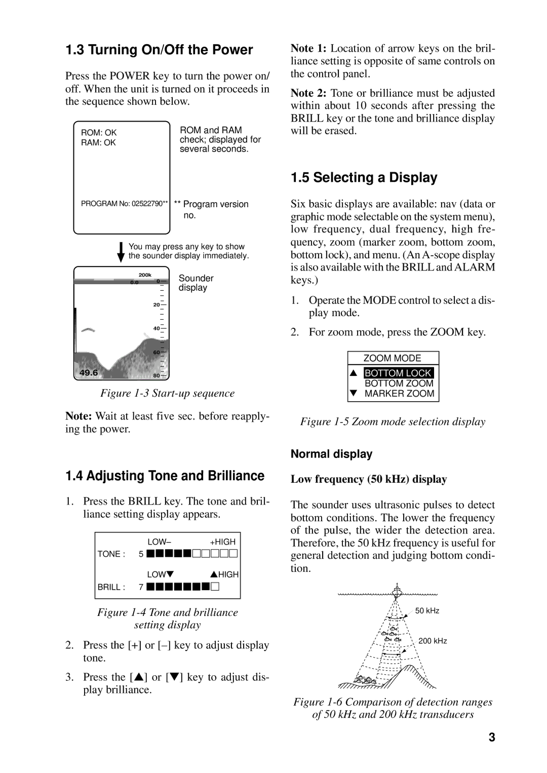
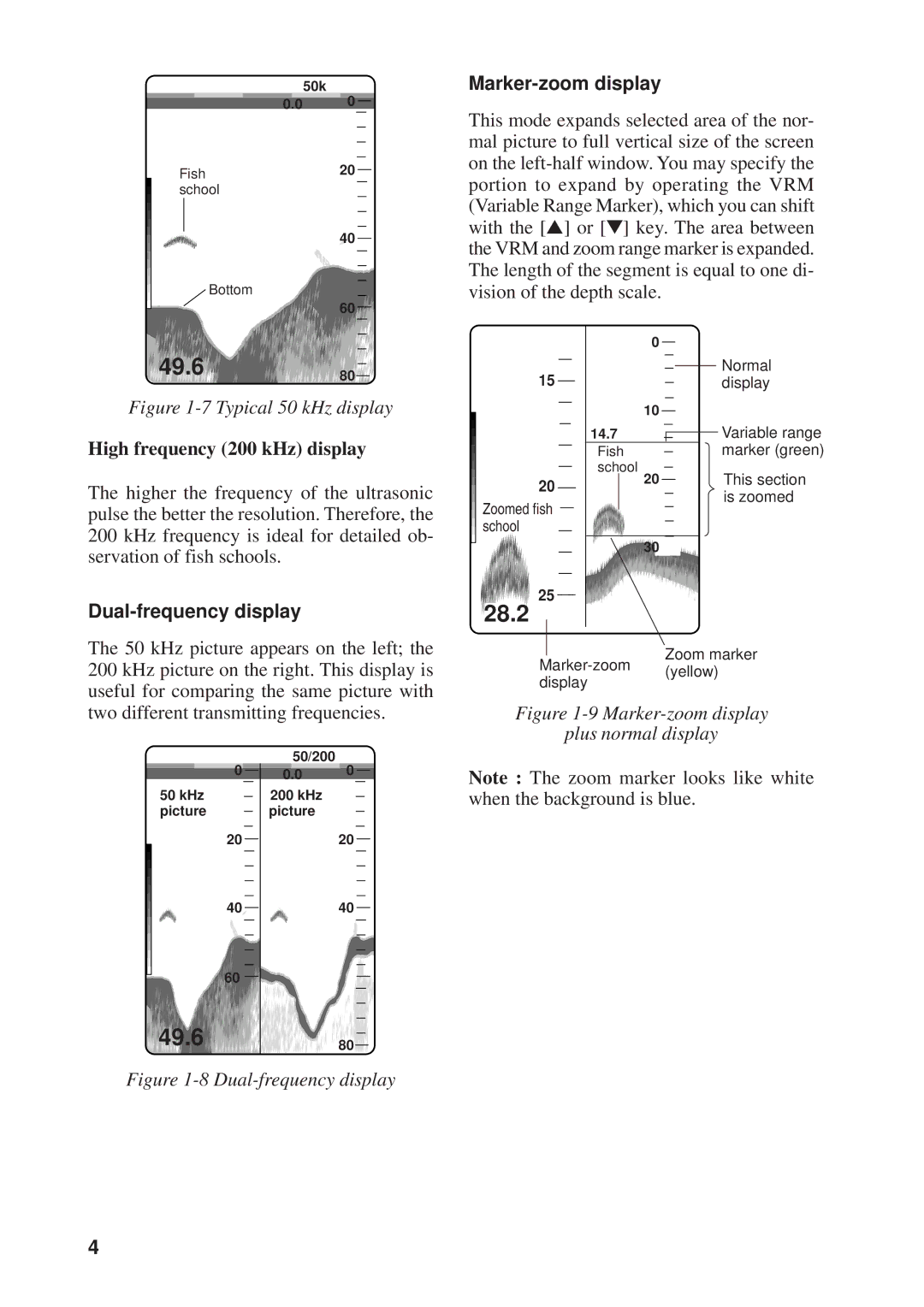
Set the MODE control in the NAV position to show the data display or the graphic display. You can select which display to show on the System menu 1, and the default setting is the graphic display 1. For how to preselect the display to show see page 15.
1.6 Selecting Display Range
The basic range and range shifting functions used together give you the means to select the depth you can see on the screen. The basic range can be thought of as providing a “win- dow” into the water column and range shift- ing as moving the “window” to the desired depth. Note that the RANGE control is inop- erative in automatic operation. (See the next page for details.)
Shift ![]()
Display
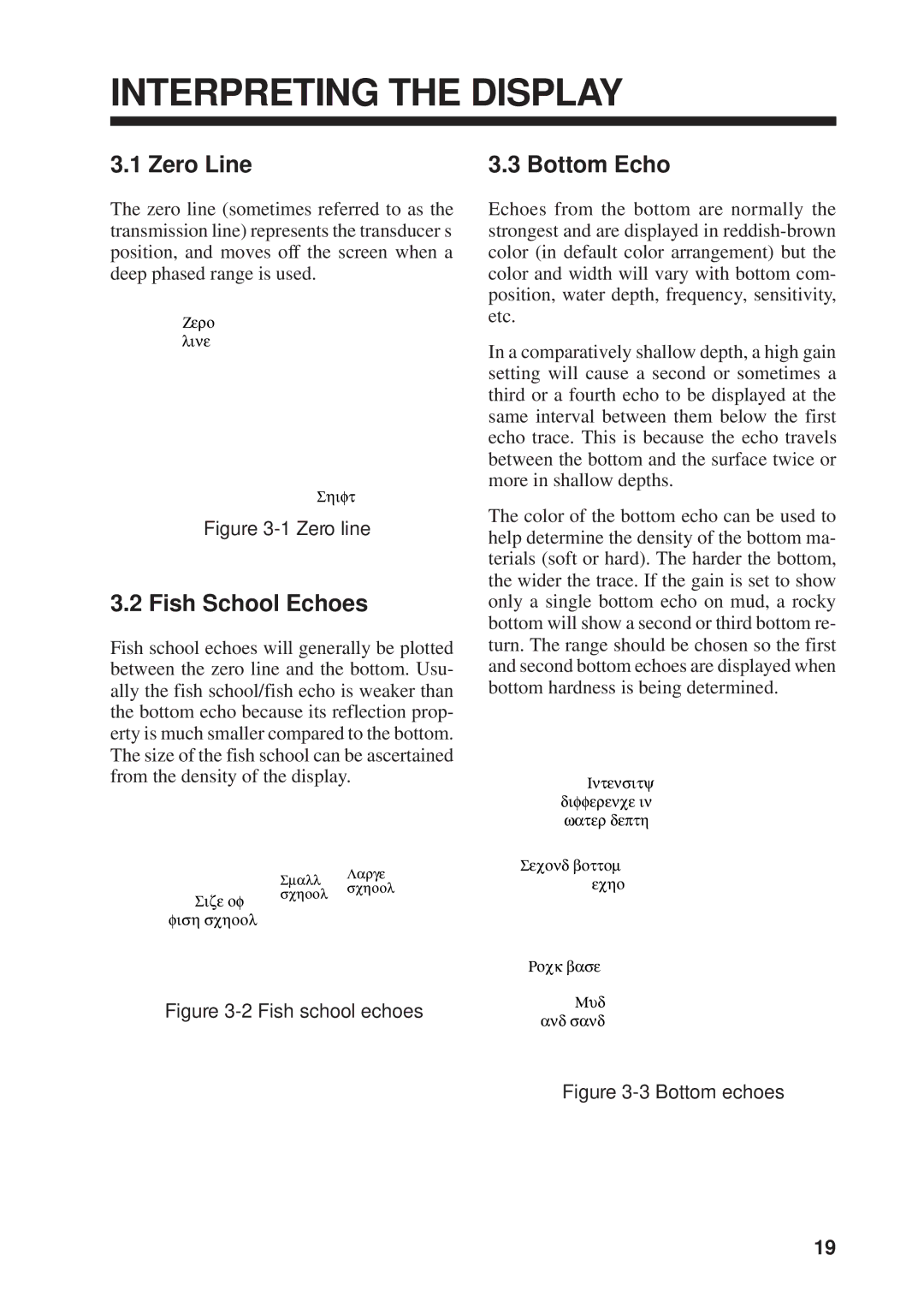
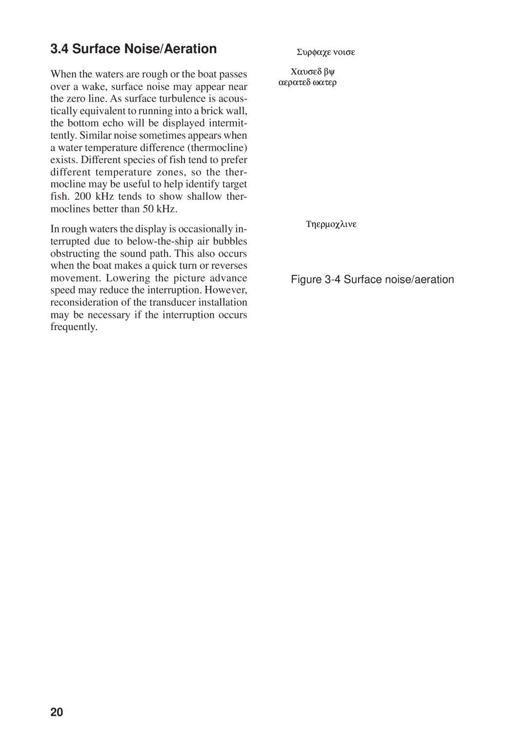
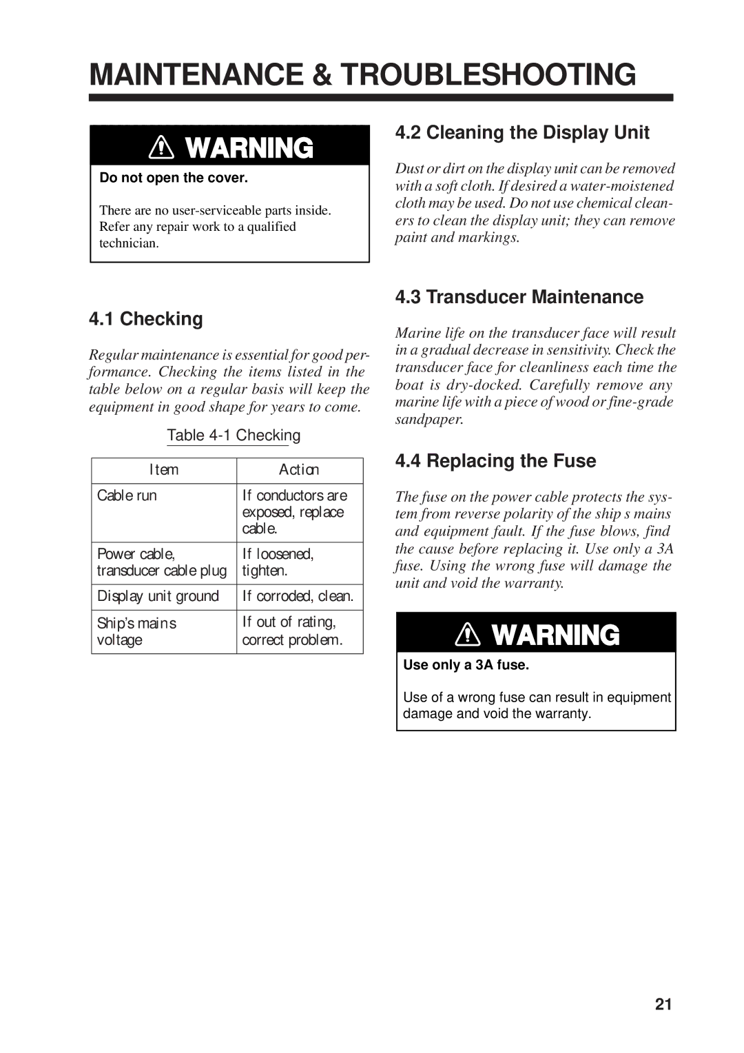
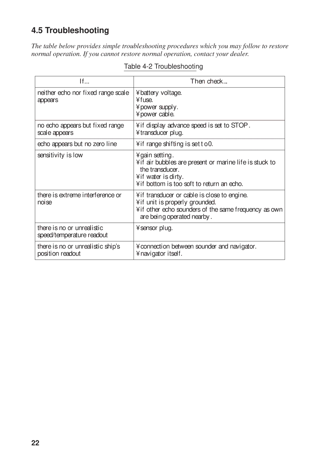
Figure 1-15 Range and display shift concept
Basic range selection
The basic range may be selected by the RANGE control from the eight ranges shown in the table below.
Table 1-1 Basic ranges (default settings)
Unit |
|
|
| Display Range |
|
| |||
|
|
|
|
|
|
|
|
| |
1 | 2 | 3 |
| 4 | 5 | 6 | 7 | 8 | |
|
| ||||||||
|
|
|
|
|
|
|
|
|
|
Meters | 5 | 10 | 20 |
| 40 | 80 | 150 | 300 | 800 |
|
|
|
|
|
|
|
|
|
|
Feet | 15 | 30 | 60 |
| 120 | 200 | 400 | 1000 | 2500 |
|
|
|
|
|
|
|
|
|
|
Fathoms | 3 | 5 | 10 |
| 20 | 40 | 80 | 150 | 400 |
|
|
|
|
|
|
|
|
|
|
Passi/Braza | 3 | 5 | 10 |
| 30 | 50 | 100 | 200 | 500 |
|
|
|
|
|
|
|
|
|
|
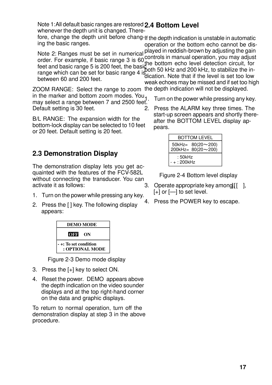
Operate the RANGE control to select a basic range. Current selection is shown in the range display window.
RANGE 5m
Figure 1-16 Range display
Range shifting
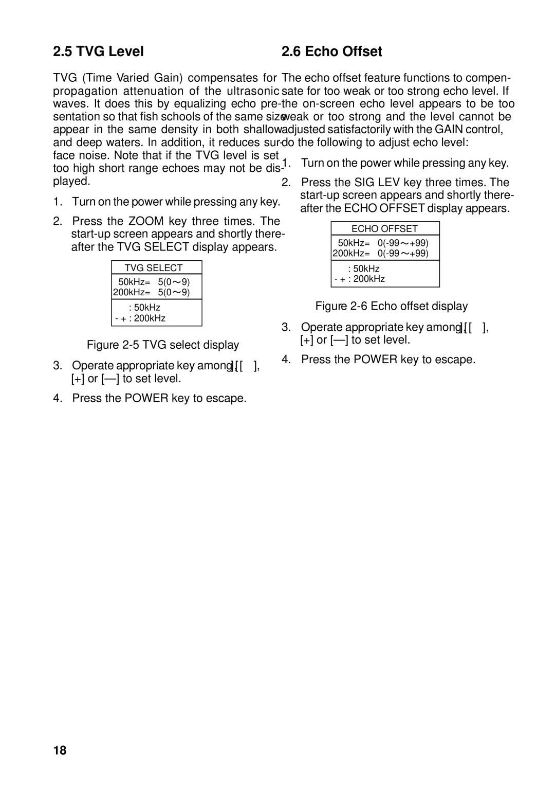
The basic range may be shifted with the [+] and
SHIFT 0m
Figure 1-17 Shift display
Note: The maximum shift range is 2500 feet (500 m). However, the actual range will de- pend on underwater conditions. In the worst case echoes will not appear.
1.7 Adjusting the Gain
The GAIN control adjusts the sensitivity of the receiver. Adjust the control so that a slight amount of noise remains on the screen. Gen- erally, use a higher gain setting for greater depths and a lower setting for shallower wa- ters. Note that the GAIN control is inopera- tive in automatic operation.
Gain too high | Gain proper | Gain too low |
Figure 1-18 Examples of proper and
improper gain
7
